
Simple Square Wave Generator with 7400

The square wave generator circuit utilizing the 74LS00 integrated circuit is designed around the principles of oscillation and timing. The 74LS00 contains four NAND gates, which can be configured to create a stable oscillator circuit. In this configuration, three of the NAND gates are employed to form an astable multivibrator, while the fourth gate may be used for additional logic functions or as a buffer.
The frequency of oscillation is primarily determined by the values of the resistors (R) and capacitors (C) used in the circuit. The time period of the square wave (T) is given by the formula T = 0.7 * (R1 + 2R2) * C, where R1 is the resistor connected to the capacitor, and R2 is the resistor connected to the feedback loop. The frequency (f) can then be calculated as f = 1/T, allowing for adjustments to achieve the desired output frequency within the specified range of 20 Hz to 1 MHz.
To ensure stable operation, it is crucial to select resistors and capacitors with appropriate tolerances and temperature coefficients. Additionally, the circuit design should account for the propagation delay of the logic gates, which can affect the timing of the output waveform. The propagation delay (tpn) is the time taken for the output to respond to a change in the input, and it is essential to maintain the condition fo < 1/2tpn to ensure reliable oscillation without distortion.
Overall, the square wave generator circuit using the 74LS00 is a versatile and effective solution for generating square wave signals, suitable for various electronic applications, including clock signals, waveform generation, and testing purposes. Proper design considerations, including component selection and layout, will enhance the performance and reliability of the circuit.This is a very simple square wave generator circuit built with IC 74LS00 that can generate square signals with frequencies between 20 Hz and 1 MHz. Its stability is good enough for most applications. The output freq. is dimensioned through the RC components and time delay of the 3 inverter gates. The time delay of a logic gate is the elapsed time between a change of input state and the resulting change of the output state. To prevent the temperature and voltage supply from affecting the frequency of the square wave generator, the oscillator freq. fo must be smaller than 1/2tpn where: 🔗 External reference
Related Circuits
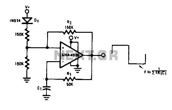
This self-starting fixed frequency oscillator circuit provides excellent frequency stability. R1 and C1 form the frequency-determining network, while R2 supplies regenerative feedback. Diode D1 improves stability by compensating for the difference between Voh and Vsupply. In applications requiring a...
Most inverters available in the market utilize a modified sine wave to achieve better output at a competitive cost. The modified sine wave unit employs a 50% fixed PWM square wave, with the peaks balanced by a capacitor to...
This 1 channel infrared transmitter/receiver remote control is the cheapest and simplest you can find. The transmitter transmits a sequence of pulses on 36 KHz frequency carrier. The diodes are Schottky type because of their low voltage drop (only...
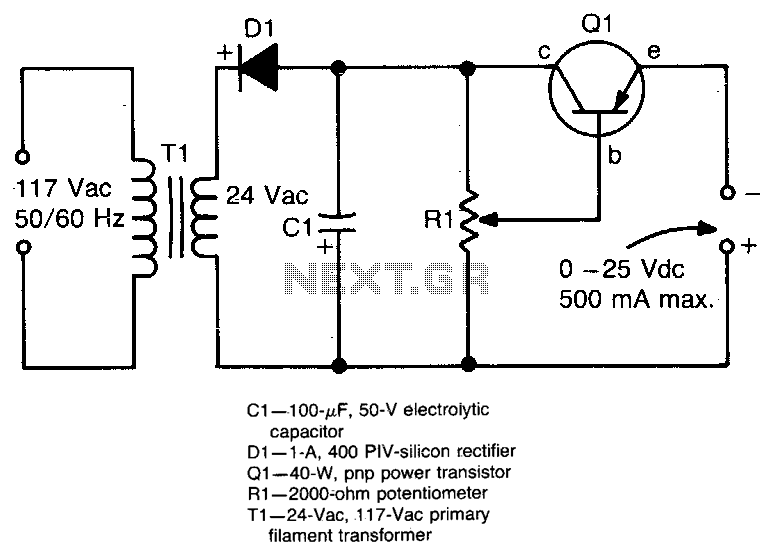
This circuit provides an adjustable output voltage of up to 35 V DC with a maximum output current of 50 mA. The transistor Q1 dissipates significant heat and must be mounted on a heatsink. The circuit in question is designed...
An adaptable siren generator circuit with multiple applications is presented. It is based on a 556 twin-timer chip, IC1. One timer section generates an audio tone that is directly coupled to the driver transistor, TR1. The other half of...
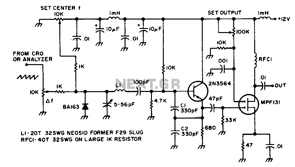
This circuit is utilized to observe the response of an intermediate frequency (IF) amplifier or a filter. It can be employed with an oscilloscope or, for a broader dynamic range, with a spectrum analyzer. The circuit designed for observing the...