
simplest modified sinewave inverter without microcontroller
The modified sine wave inverter circuit operates by utilizing a combination of a 4017 decade counter and a 555 timer IC to generate the necessary control signals for the MOSFETs. The 4017 decade counter is configured to produce four distinct output pulses, corresponding to the four phases of the modified sine wave. Each pulse generated by the 4017 corresponds to specific voltage levels that define the quasi-sine wave shape. The 555 timer is configured in astable mode to provide the required clock frequency, which is critical for the operation of the 4017.
To implement this design, the 555 timer output is set to oscillate at 200Hz, which allows the 4017 to cycle through its outputs, generating the necessary pulse sequence. The two non-consecutive outputs from the 4017 are connected to the gates of the MOSFETs in a push-pull configuration. This arrangement enables the MOSFETs to switch on and off in a manner that effectively simulates the desired modified sine wave output.
The use of capacitors in conjunction with resistors is essential for shaping the output waveform. The capacitor smooths the transitions between the square wave pulses, reducing the sharp edges and creating a waveform that more closely resembles a sine wave. This process is critical for minimizing the total harmonic distortion and improving the overall quality of the inverter output.
In summary, the circuit design for a modified sine wave inverter using a 4017 decade counter and a 555 timer is a practical approach to achieving efficient power conversion. The careful selection of components and configuration of the circuit ensures that the inverter can deliver a stable output while maintaining a competitive cost. The final output requires the integration of MOSFET pairs with the oscillator outputs to effectively drive the inverter transformer, completing the design for a functional modified sine wave inverter.Most of the inverters in the market uses modified sinewave for better output at competitive cost. The modified sinewave unit uses a 50% fixed PWM squarewave and the hikes are balanced by a capacitor to produce almost a sine wave. This is called quasi sinewave having THD around 25-28% while squarewave inverters have 45% THD and pure sinewave invert
ers have just 3% THD. So, to form a modified sinewave inverter of 220V, we have to generate a 4 phase signal which has 25% 0V, 25% +311V, 25% 0V and 25% -311V. Thus, by series resistor-ed capacitor, the waveform becomes a quasi sinewave. In the driving section of push pull MOSFET sets (2 sets) we have to provide the following pulse, Now this requires a controlled bistable multivibrator whose output is set to off in 50% time.
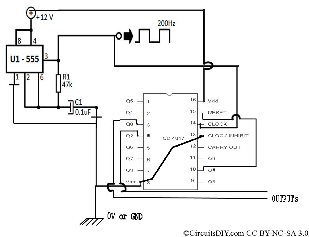
But we will use here a simple replacement for that. It`s a 4017 decade counter IC. We`ll use it to generate 4 pulses and the fifth state would be reset and this creates our required pulse. Then we just connect two non-consecutive outputs to MOSFET section to generate output. But there`s a tricky part in the clock and frequency. Since 4017 decade counter IC don`t have inbuilt clock generator, it requires external CP. For this we`ll use 555 timer IC and for each CP the output changes one step, but we need 4 changes for a complete 360 ° cycle.
Hence, to make a 50Hz output, we need to set 555 timer IC to 200Hz. Please note that following circuit only shows upto outputs from oscillator, you need to connect MOSFET pairs at the outputs for driving the Inverter Transformer. 🔗 External reference
Related Circuits
This project measures the clock pulses supplied to the Timer input of the AVR microcontroller. The Bascom code counts the clock pulses over a duration of 1 second and displays the result. The circuit for this project primarily consists of...
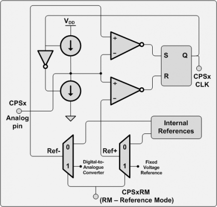
There are numerous applications for this hardware, including touch pads, proximity sensors, capacitive sensor readouts, high-precision capacitance measurements, ultra-small capacitance change detection, soil moisture sensing, and skin moisture measurement, among others. However, after searching for examples, it was surprising...
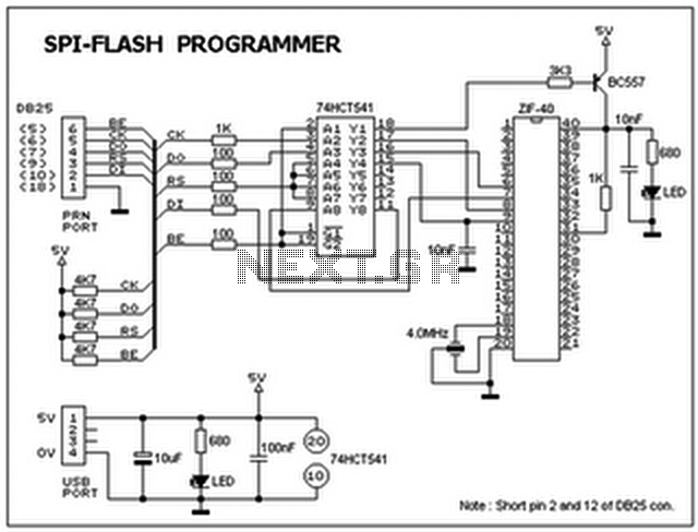
This ISP programmer can be utilized for both in-system programming and as a standalone SPI programmer for Atmel ISP programmable devices. The programming interface is compatible with the STK200 ISP programmer hardware, allowing users of STK200 to employ the...
This circuit is designed to convert 12V DC into 220V AC. It utilizes a 4047 integrated circuit to generate a 50Hz square wave, which is then amplified for current and voltage using a step-up transformer. The fundamental relationship between...
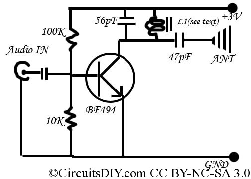
This is a simple and inexpensive FM transmitter. The circuit operates at a low voltage using a CR2025 3V battery with low current consumption. The total size of this FM transmitter, including the battery but excluding the antenna, is...
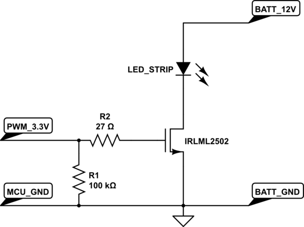
A strip of LEDs is controlled by a microcontroller using pulse-width modulation (PWM) to adjust brightness. The LED strip requires approximately 1.5A at 12V. The user, who has experience only with low-power digital electronics, seeks confirmation of their assumptions...