
SIREN GENERATOR CIRCUIT
The adaptable siren generator circuit utilizes the NE556 dual timer integrated circuit (IC1) as its core component, which allows for flexibility in audio signal generation. The first timer section functions as an audio oscillator, producing a continuous tone that is amplified by the transistor TR1, which serves as the output driver. The modulation of this tone's frequency is achieved through the second timer section, which interfaces with the CONTROL VOLTAGE pin (pin 11) of the audio oscillator. This setup enables the generation of varying tones, making it suitable for alarm systems or signaling devices.
In its basic configuration, omitting capacitor C2 transforms the circuit into a twin-tone alarm generator, which can be useful in applications requiring distinct sound alerts. Conversely, including C2 introduces a "wailing" sound effect, enhancing the alarm's urgency. The capacitor C1 is critical for determining the frequency modulation rate, allowing for customization of the tone's responsiveness to control voltage changes.
The visual aspect of the circuit is complemented by LED D1, which provides a flashing indication that synchronizes with the audio output, improving the overall alerting capability of the device. The loudspeaker LS1 is a waterproof Mylar-coned 8-ohm type, chosen for its durability and sound quality in outdoor or challenging environments. The volume output can be fine-tuned by adjusting resistor R5, allowing for compatibility with various loudspeaker impedances and ensuring optimal performance in different operational settings.
This siren generator circuit is powered by a 9-V source, making it suitable for battery-operated applications or low-voltage power supplies. Overall, the design offers versatility and adaptability for a range of signaling and alarm applications, with the potential for further modifications to meet specific requirements.An adaptable siren generator circuit with a multitude of uses is shown. It is based around a 556 twin-timer chip, IC1. An audio tone is created by one timer section and is directly coupled to the driver transistor, TR1. The other half of the timer is used to modulate the frequency of the audio tone using the CONTROL VOLTAGE pin terminal of the audio-oscillator section, pin 11.
(NE556 TIP41A) If capacitor C2 is omitted from the circuit, a twin-tone alarm generator will be created. However, with C2 in place as shown, a "wailing" tone is produced. Capacitor C1 governs the rate of tone change and LED D1 flashes for extra effect. A waterproof Mylar-coned 8-Ω loudspeaker was used for LS1, and the volume can be adjusted for different impedances by altering the value of resistor R5.
The circuit operates from approximately a 9-V rail.
Related Circuits
An increasing number of appliances draw a very small current from the power supply. If designing a mains-powered device, one can generally choose between a linear and a switch-mode power supply. However, when the appliance's total power consumption is...
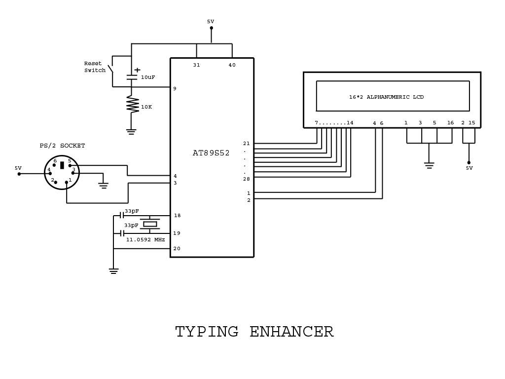
Project with Circuit and Code for a Typing Assistant using the 8051 microcontroller (AT89S52) and the PS/2 keyboard port of a computer. The project also explains the interfacing of the PS/2 port of a computer with the 8051 microcontroller. The...
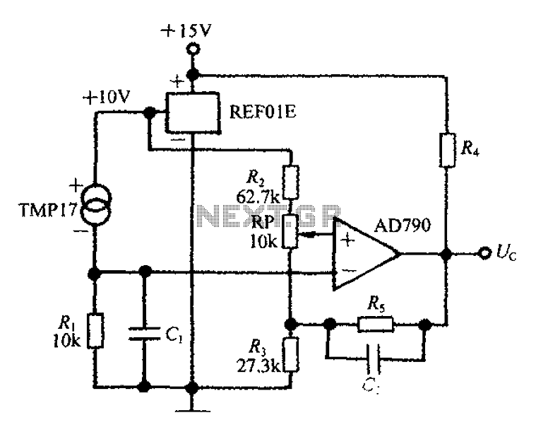
An adjustable thermostat controller circuit is widely used in everyday applications, such as for maintaining a constant temperature in soldering irons. The circuit utilizes the TMP17 sensor along with the REF01E voltage reference to ensure a stable 10V supply...
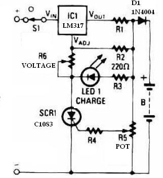
This schematic circuit for a battery charger consists of very few components but operates effectively. When power is applied to the circuit, SCR1 remains off, preventing any bias current from flowing to ground. The LM317 voltage regulator is connected...
The following circuit illustrates a simple stepper motor controller circuit diagram. This circuit is based on the 7404 integrated circuit. Features include suitable heat dissipation. The simple stepper motor controller circuit utilizes the 7404 hex inverter IC to control the...
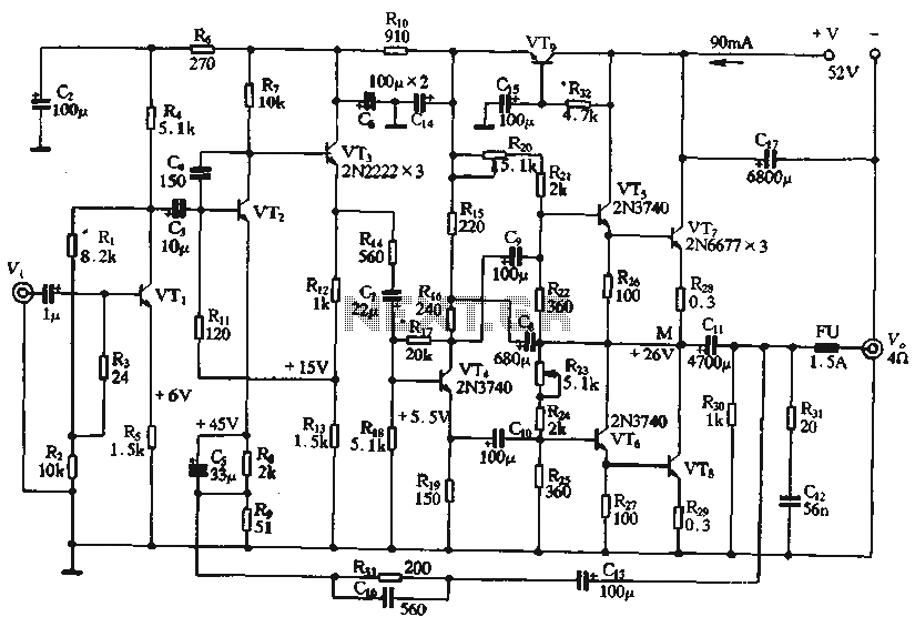
The circuit depicted in the figure is a highly technical OTL (Output Transformer-Less) amplifier circuit. It features a frequency response range of 10 Hz to 100 kHz and exhibits a total harmonic distortion of less than 0.1%, which is...
Warning: include(partials/cookie-banner.php): Failed to open stream: Permission denied in /var/www/html/nextgr/view-circuit.php on line 713
Warning: include(): Failed opening 'partials/cookie-banner.php' for inclusion (include_path='.:/usr/share/php') in /var/www/html/nextgr/view-circuit.php on line 713