
Simple strobe circuit
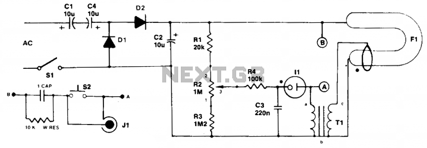
The described circuit operates as a strobe light generator, utilizing neon and xenon lamps for illumination. Initially, both lamps remain off, presenting high resistance, which allows capacitors C1 and C4 to charge through the voltage doubler configuration formed by diodes D1 and D2. This charging process continues until the voltage across capacitor C3 reaches the ionization potential of neon bulb II, at which point the bulb begins to conduct. The transition from non-conductive to conductive state results in a rapid decrease in resistance, allowing a significant current pulse to flow through the primary winding of transformer T1.
The transformer is designed with a specific turns ratio that steps up the voltage to approximately 400 V on the secondary side, which is essential for the operation of the xenon tube. This tube, unlike the neon bulb, requires an external high-voltage signal (4 kV) to ionize the gas and initiate conduction. Once the xenon tube conducts, it generates a bright flash of light, which is characteristic of strobe lighting applications.
The circuit's operation is cyclical. When fuse F1 conducts, it discharges capacitor C2, resetting the system and allowing the charging process to begin anew. Resistor R2 plays a critical role in controlling the charge rate of capacitor C3, which in turn affects the frequency of the strobe light flashes. By adjusting the resistance, the user can modify the repetition rate of the strobe effect, allowing for customization of the lighting output based on the application's requirements. This design is commonly employed in various lighting applications, including photography, entertainment, and signaling, where precise timing and bright flashes are needed.Initially the neon and xenon lamps are not conducting and act like a very high (almost infinite) resistance. Capacitors Cl and C4 in conjunction with DI and D2 form a voltage doubler circuit, which can charge C2 up to about 300 Vdc after several ac cycles.
Voltage increases as current is supplied through Rl and R2. Neon bulb II will all of a sudden start to conduct when the voltage across C3 reaches II's ionization potential. While conducting, the resistance of the bulb will be relative low. £)ue to this sudden conduction, a pulse of current will pass through the primary of Tl. The turns ratio is such that about 400 V will be developed at the secondary. The xenon tube is similar to the neon bulb in that it produces light when the gas ionizes and conducts. However, it is designed so that an external signal (the 4 kV on the metal ring around the tube) ionizes the gas and initiates the conduction.
When F1 conducts, it discharges C2. At this point, the whole cycle starts over again. The purpose of R2 is to vary the rate at which C3 charges, and hence the repetition rate of the strobe. 🔗 External reference
Related Circuits
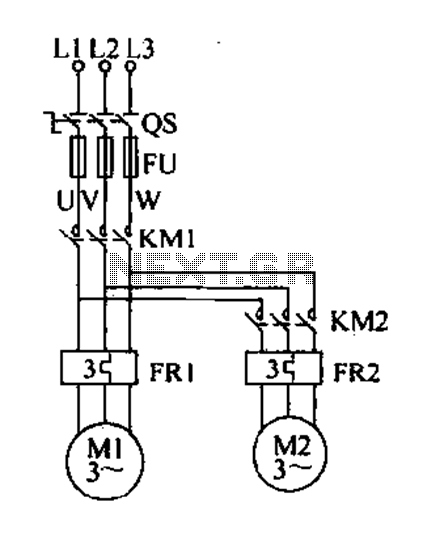
Delay starting a motor control circuit The motor control circuit designed for delayed activation incorporates a timing mechanism that ensures the motor does not start immediately upon receiving power. This is particularly useful in applications where a staggered startup...

The circuit consists of the MAX1494 and a thermocouple temperature measurement system. The MAX1494 is terminated at 1N GND 5-32. An external temperature sensor, such as the DS75, can be utilized for junction temperature compensation. The MAX1494 employs an...

A current control circuit for temperature regulation of a soldering iron utilizes a high-voltage integrated regulator, TL783 (U1). With the specified component values, this circuit is suitable for use with a soldering iron rated at 25 W or less. The...

This is an infrared-based broken beam alarm designed to protect doors and entry passages. It emits a loud alarm when someone crosses the invisible infrared barrier. The infrared-based broken beam alarm system operates by utilizing a pair of infrared emitters...
In addition to its primary function as a headphone amplifier, the circuit is suitable for various applications requiring a wide bandwidth low power amplifier. It is constructed using an operational amplifier (op-amp), with its output current enhanced by a...

The FS810 circuit serves as a practical implementation of an integrated power amplifier. The FS810 is designed for high-performance use in high-end tape recorders and audio equipment. In the schematic, the speaker is connected to the output capacitor C5...