
Soldering Iron Control Circuit
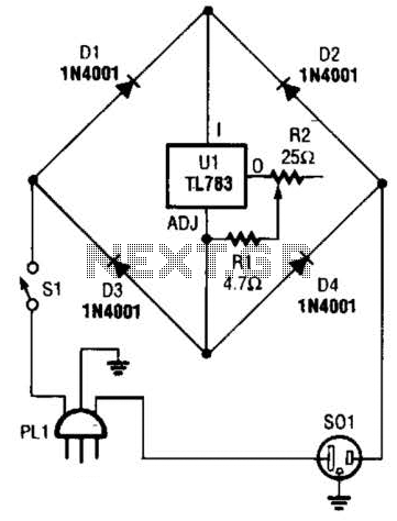
The circuit employs the TL783 voltage regulator, which is designed to provide a stable output voltage while allowing for adjustable current control. This feature is essential for maintaining the desired temperature of the soldering iron. The TL783 can handle input voltages up to 125 V and output currents of up to 700 mA, making it a robust choice for this application.
To implement this circuit, several key components are required. The input voltage should be appropriately selected based on the power supply available, ensuring it remains within the operational limits of the TL783. The output voltage can be adjusted using a potentiometer connected to the adjust pin of the regulator, allowing for fine-tuning of the soldering iron's temperature.
Additional components may include capacitors for stability and filtering, as well as resistors to set the desired output voltage. It is critical to choose these components based on the specific characteristics of the soldering iron being used. For a 25 W soldering iron, the output current should be limited to approximately 1 A, which can be achieved by selecting appropriate resistor values in the feedback loop of the TL783.
Thermal management is also a crucial consideration in this circuit design. The TL783 may require a heatsink to dissipate heat generated during operation, especially when operating near its maximum current rating. Proper layout and thermal considerations will enhance the reliability and performance of the soldering iron temperature control circuit.
Overall, this current control circuit provides an effective means of regulating the temperature of a soldering iron, ensuring optimal performance for soldering applications. A current control to temperature regulate a soldering iron uses a high-voltage integrated regulator, TL783 (Ul). With the component values specified, the circuit should be used with a soldering iron of 25 W or less. 🔗 External reference
Related Circuits
Delay electronic doorbell circuit - touch doorbell amplifier circuit The delay electronic doorbell circuit is designed to provide a user-friendly interface for doorbell activation, utilizing a touch-sensitive amplifier circuit. This circuit typically incorporates a touch sensor that detects user interaction,...
To initiate the process, the LOAD switch and Reset switch must be pressed simultaneously within 24 seconds; otherwise, the countdown will commence from 99. A pulse input can be connected to a 555 astable multivibrator, but it must be...
To extend the measurement range of an available ADC (analog to digital converter), autoranging can be utilized. If implemented on multiplexed input, this... Autoranging is a technique employed in electronic measurement systems to automatically adjust the range of an analog-to-digital...
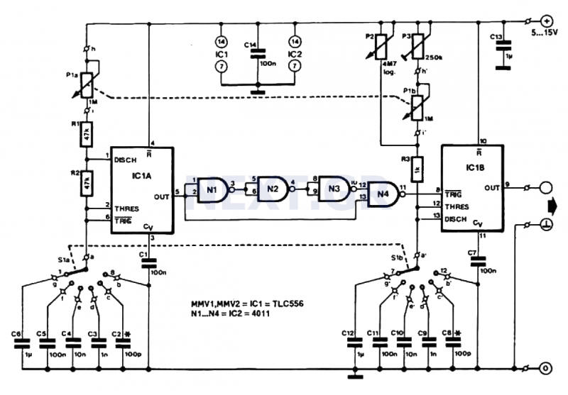
This pulse generator produces square pulses ranging from 1Hz to 100KHz with an adjustable pulse width of nearly 0-100%. It operates on a voltage of 5-15V, making it suitable for both TTL and CMOS circuits. This device is essential...
This schematic represents an FM transmitter capable of delivering an output power of 3 to 3.5 W, operating within a frequency range of 90 to 110 MHz. While the stability of the circuit is acceptable, the integration of a...
A step-down circuit is utilized to approximately halve the RMS voltage between the line input and the inductive load (L1), as illustrated in the circuit diagram below. A turn-on delay of about 7 ms is achieved through the combination...