
servo speed tester
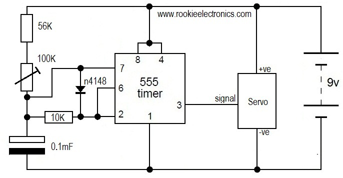
The described circuit functions as a basic servo motor tester, primarily aimed at evaluating the operational speed and position of a servo motor. The circuit employs a 555 timer configured in astable mode, generating a pulse-width modulation (PWM) signal that controls the servo's movement.
Key components include a potentiometer, which serves as a variable resistor, allowing for fine adjustments to the voltage supplied to the servo. By varying the resistance, the effective voltage and current reaching the servo can be altered, thus controlling the speed at which the servo rotates. The use of a 4.5V power supply is suitable for most standard servos, ensuring safe operation without exceeding the motor's voltage ratings.
Additionally, the circuit incorporates two push buttons that facilitate manual control over the servo's direction. One button is designated for clockwise rotation, while the other is for counterclockwise rotation. When pressed, these buttons send a signal to the 555 timer, which then adjusts the duty cycle of the PWM signal, effectively changing the rotation direction of the servo.
This simple yet effective circuit serves as an educational tool for understanding servo mechanics, PWM control, and the operation of the 555 timer in practical applications. It is suitable for hobbyists and beginners in electronics, providing hands-on experience with servo motors and basic circuit design.This is probably the simplest Circuit to test a Servo, This circuit tests the speed of servo. Here we use potentiometer to controll the speed of the servo. By applying very less voltage like 4. 5V and reducing the pot value, you can also adjust the position of the servo! Check this Circuit which uses push switches to run a servo in Clock-wise and a nti Clock-wise directions using 555 timer 🔗 External reference
Related Circuits
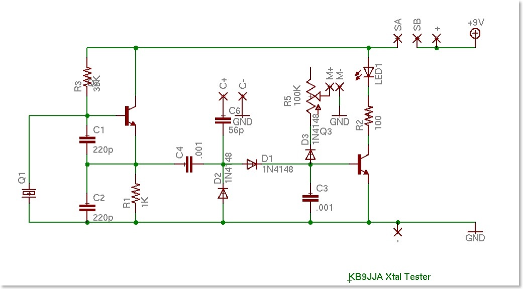
A crystal tester was developed to evaluate various crystals for a project. Existing testers available online were found to be lacking in certain features. Therefore, modifications were made to an existing design to incorporate desired functionalities, along with the...
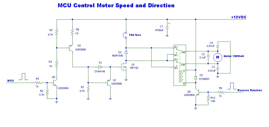
This is a power motor controller circuit designed for 12V applications. It utilizes a microcontroller unit (MCU) for signal control, operating at a high voltage level of approximately 3V. The circuit allows for the motor to be controlled to...
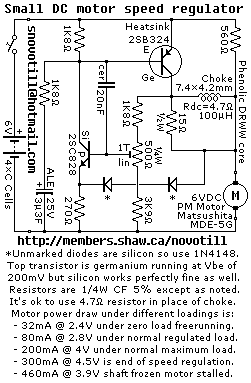
Reverse engineered circuit diagram of a motor speed regulator out of a portable pocket tape recorder containing a single motor for all functions. This circuit works amazingly well, keeping the motor speed constant regardless of shaft load and battery...
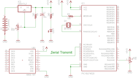
There are two schematics to examine for constructing a transmitter/receiver system. The first schematic is the transmitter, featuring a variable trimpot connected to RA0. The trimpot's value will be transmitted from the Tx pin of the PIC to the...
This must be the most efficient bipolar transistor motor driver design for this application and I recommend it for the solar roller competitions. A 1381E is used to trigger at 2.4V. While it takes a total of 10 components...
The circuit presented on this page attempts to be an interface to convert pulses such as provided by a Basic Stamp or R/C receiver to a dual PWM (Pulse Width Modulation) signal required by an H-bridge. The simplest circuit...
Warning: include(partials/cookie-banner.php): Failed to open stream: Permission denied in /var/www/html/nextgr/view-circuit.php on line 713
Warning: include(): Failed opening 'partials/cookie-banner.php' for inclusion (include_path='.:/usr/share/php') in /var/www/html/nextgr/view-circuit.php on line 713