
Simple Telephone Ring Tone Generator Circuit schematic with explanation

The telephone ringtone generator circuit is built around the CMOS IC CD4060B, which integrates both a binary ripple counter and an oscillator. This dual functionality allows for efficient generation of the required pulse frequencies necessary for simulating the ringtone. The output frequencies are determined by the configuration of the oscillator and the counter stages.
The circuit's operation begins with the application of a DC voltage supply, which can vary between 4.5V to 12V. The choice of supply voltage directly influences the loudness of the ringtone, with +12V providing the maximum sound output. The adjustable volume feature is typically implemented using a variable resistor (VR1), which allows fine-tuning of the pulse width and thus the perceived loudness of the ringtone.
The pulses generated at the output pins of the CD4060B are characterized by their duty cycles and frequencies. The output from pin 3 produces a low frequency of 0.3125Hz, which is suitable for creating the characteristic ringing sound of a telephone. The output from pin 1 generates a frequency of 1.25Hz, which can be used for different ringing patterns, while pin 14 outputs a faster frequency of 20Hz, contributing to the overall sound dynamics.
Transistors T1, T2, and T3 serve as amplifiers in this circuit, boosting the current from the output pins of the CD4060B to drive a speaker or buzzer effectively. Resistors R1, R2, and R3 are crucial in limiting the base current to the transistors, ensuring they operate within their safe limits while still providing sufficient gain to produce a loud sound.
This simple yet effective design is ideal for various applications, including intercom systems, where a clear and adjustable ringing tone is required. Its reliance on standard components makes it accessible for hobbyists and engineers alike, providing an excellent project for those interested in audio signal generation and control using basic electronic principles.This is the figure simple telephone ring tone generator circuit designed using only a few components. It produces simulated telephone ring tone and needs only DC voltage (4. 5V DC to 12V DC). One may use this circuit in ordinary intercom or phone-type intercom. This is the figure of the circuit; The sound is quite loud when this circuit is operated on +12V DC power supply. However, the volume of ring sound is adjustable. The commonly available 14-stage binary ripple counter with built-in oscillator (CMOS IC CD4060B) is used to generate three types of pulses, which are available from pin 1 (O11), pin 3 (O13), and pin 14 (O7), respectively. Preset VR1 is adjusted to obtain 0. 3125Hz pulses (1. 6- second low` followed by 1. 6-second high`) at pin 3 of IC1. At the same time, pulses available from pin 1 will be of 1. 25 Hz (0. 4-second low`, 0. 4-second high`) and 20 Hz at pin 14. The three output pins of IC1 are connected to base terminals of transistors T1, T2, and T3 through resistors R1, R2, and R3, respectively.
🔗 External reference
Related Circuits
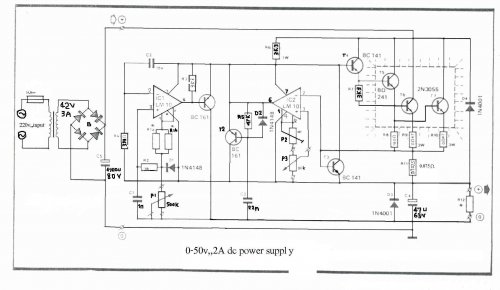
The LM10 integrated circuit (IC) is utilized due to its reference voltage feature, which is advantageous for DC power supply applications. By employing two LM10 ICs, different output voltages and current levels can be achieved. This circuit includes short-circuit...
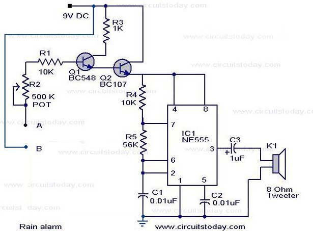
The operation of the rain alarm circuit is explained in detail. The rain alarm project is outlined along with a circuit diagram. The rain alarm circuit is designed to detect the presence of rain and alert users through an audible...
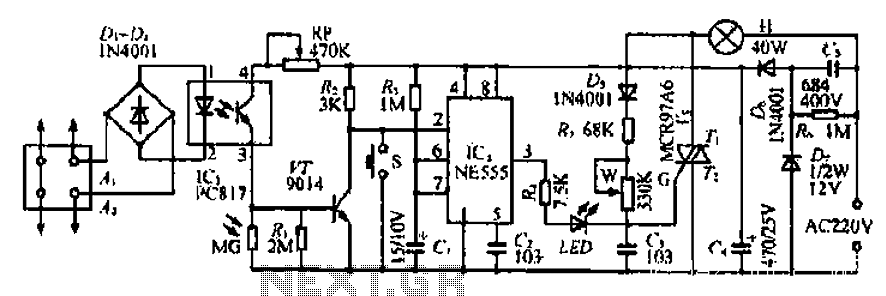
The Ai. A2 series operates with a telephone line, where sound anomalies or off-hook currents activate a light within an arc tube, which in turn triggers a photosensitive MOSFET. This process involves a saturated conduction base voltage that sends...
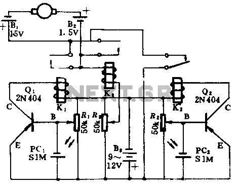
In the absence of light, photocells PC1 and PC2 exhibit high resistance, causing transistors Q1 and Q2 to remain off, which prevents the relay contacts K1 and K2 from closing. The battery B3 is connected through a potentiometer Rs,...
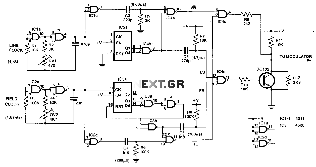
This circuit serves as a simple, low-cost crosshatch generator for convergence and geometry adjustments in color televisions. It is driven by two clock signals, one for horizontal drive (IC1ab) and another for vertical drive (IC2ab). The outputs from these...
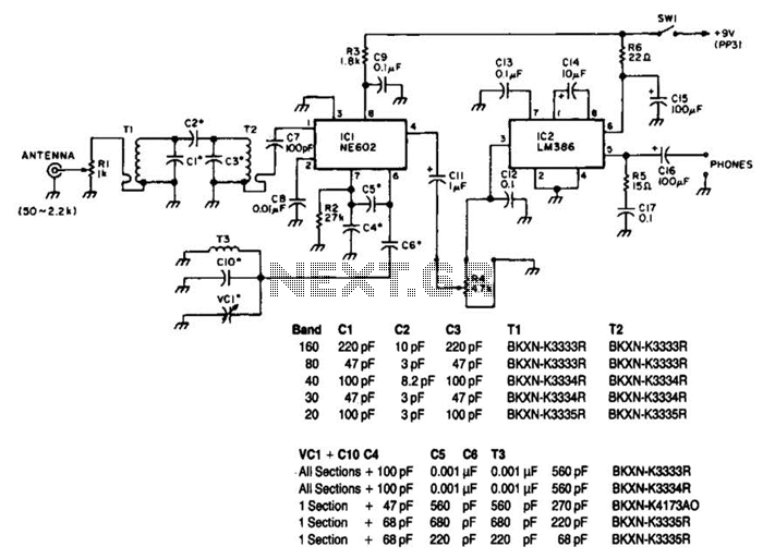
Note that T1 and T2 are TOKO components, including part numbers for the coils T1 and T2. The direct-conversion receiver shown utilizes a double-tuned input network made from readily available TOKO coils. IC1, an NE602, serves as a voltage-controlled...