
Simple Parallel (Printer) Port Interface
 Port Interface")
The described parallel interface serves as a fundamental component in a computerized room control system, allowing for the integration of various electronic devices and sensors. The design is based on an 8-bit input card, which facilitates the reading of multiple digital signals simultaneously. This is particularly advantageous for applications such as robotics, where multiple inputs can dictate the behavior of motors or sensors.
The choice of a universal solder board for assembly is pragmatic, as it provides flexibility in the layout and easy troubleshooting capabilities. The high density of connections typically required in such projects can lead to complex wiring arrangements, making a universal board a suitable choice over a more rigid printed circuit board (PCB). The use of a 25-pin crimp connector to interface with the parallel port ensures a reliable physical connection, which is critical for maintaining signal integrity across the interface.
In terms of electrical specifications, the parallel interface operates within the standard voltage levels defined for TTL (Transistor-Transistor Logic) devices, typically around 5V. Care should be taken to ensure that the connected devices are compatible with these voltage levels to avoid damaging components. Additionally, the design should include proper grounding and shielding practices to minimize electromagnetic interference, which can adversely affect performance.
When constructing the interface, it is advisable to follow a schematic diagram that outlines the connections between the input card and the parallel port. This diagram should include details such as pin assignments, resistor values, and any necessary capacitors for signal stabilization. Testing the interface on a non-critical system, such as a school computer, is recommended to mitigate any risks associated with incorrect connections, especially considering the variability in protection mechanisms across different parallel ports.
Overall, this parallel interface design exemplifies a cost-effective and accessible solution for hobbyists and educators interested in exploring computerized control systems and robotics.This is the basic interface I used as part of my Computerized Room project. This is the parallel interface only. The 8 bit input card can be found, along with the rest of the project, at Computerize Your Room/House. This interface, as well as the other two interfaces, came from the book "The Robot Builders Bonanza", by Gordan McComb.
This interface is also useful for controlling small robots, etc. It is cheap and fairly easy to build, although you should not attempt this project unless you have prior experience with electronics. You probably won`t damage anything if you hook it up wrong, but there is always a chance (some parallel ports are better protected then others).
If possible, test the project on someone else`s, or a school computer # I built the interface on a piece of universal solder board due to the large number of wires that must cross. It is also much easier to fix mistakes then on a PC board. I also used a 25 pin crimp connector to connect it to the parallel port. 26 conductor 🔗 External reference
Related Circuits
A 12V battery charging circuit is presented, featuring a straightforward diagram for a rectifier. The lead-acid trickle charger circuit is detailed along with its rectifier. The 12V battery charging circuit is designed to charge lead-acid batteries using a trickle charging...
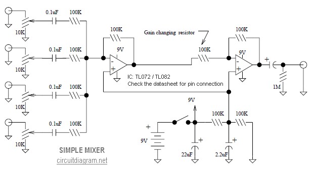
This is a simple mixer featuring four inputs and two operational amplifiers (op-amps). It is designed for mixing microphones or effects outputs. The overall gain from input to output is unity when the potentiometer associated with the input is...
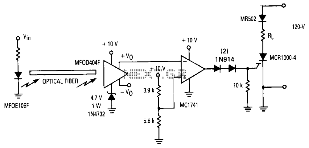
An operational amplifier (op amp) is utilized to connect a fiber optic system with a MOS SCR for multi-cycle, half-wave control of a load. This receiver features two complementary outputs: one maintains a quiescent level of approximately 0.6 V,...
This simple tuned radio frequency receiver was designed and constructed in the mid-1990s. The receiver was tested under urban and field conditions, in varying temperatures. This straightforward circuit exhibits high sensitivity, good sound quality, and reliability. A signal received...
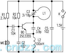
The loop antenna L1 is utilized for emission and also functions as the oscillation coil. The high-frequency current flowing through the antenna is synchronized in resonance with the oscillation frequency, ensuring optimal emission performance. Practical applications indicate that the...
%2BCircuit%2Bdiagram%2Busing%2BCD4047%2Band%2BIRFZ44%2Bpower%2BMOSFET.png)
This simple low-power DC to AC inverter circuit converts 12V DC to either 230V or 110V AC. By making simple modifications, it is also possible to convert 6V DC to 230V AC or 110V AC. This inverter can be...