
Simple Momentary Switch with 555
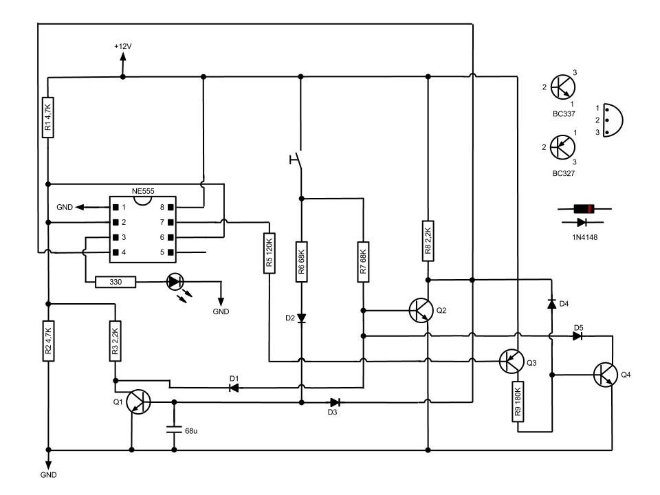
The NE555 timer is configured in a bistable mode, allowing it to toggle its output based on the state of the momentary switch. The circuit's operation begins with the momentary switch in its unpressed state, leaving the output at a low state due to the voltage levels at pins 2 and 6. When the switch is pressed, a brief pulse is generated, which is coupled through a capacitor to trigger Q1. This transistor's activation momentarily changes the voltage levels at pins 2 and 6, causing the timer's output (pin 3) to switch to a high state, illuminating the connected LED.
The role of Q2 is crucial for resetting the circuit. When the momentary switch is pressed a second time, Q2 is activated, which pulls pin 4 low. This action effectively resets the timer, allowing the circuit to return to its original state without requiring a mechanical relay. The use of a pull-up resistor on pin 4 ensures that it remains high in its default state, enabling reliable toggling behavior.
This NE555-based circuit design is particularly advantageous for automotive applications where space is limited, and the absence of mechanical components increases reliability. The use of transistors for switching reduces wear and tear compared to traditional relay systems, making this design suitable for various electronic control tasks within vehicles.Based on NE555 this circuit turns on and off the IC output by a momentary switch. In other words it works as a mechanical latching relay, but the circuit backs to the start condition when you switch off the power supply. This feature is often required in automotive devices. No relay contacts are used, infact I connected the output to a led. Once t he momentary switch circuit is supplied the output (pin 3) keeps off because pin 2 and 6 are at half voltage. When the button is pressed Q1 turns on within a fraction of second because of the capacitor, while Q2 keeps off.
By switching on Q1 leads pin 2 and 6 to low voltage, then the output gets high. When the button is pressed again Q2 switches on and leads pin 4 to low voltage (I used a pull up resistor), then the circuit takes the start condition. 🔗 External reference
Related Circuits
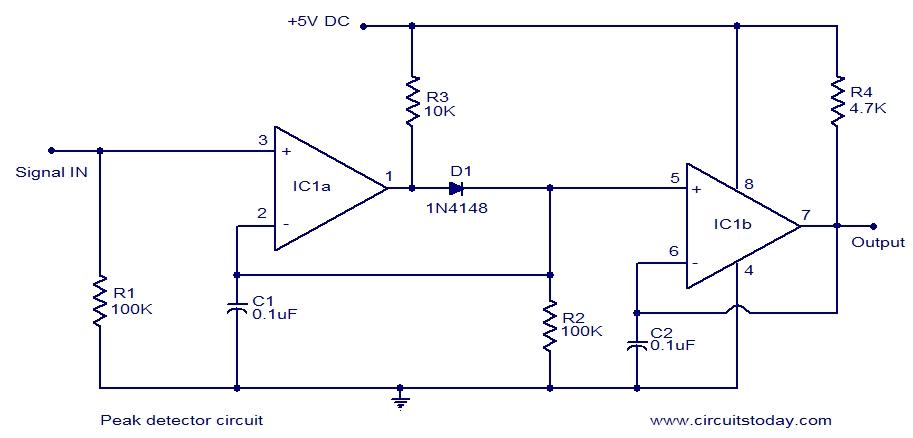
LM339-based peak detector circuit. Simple and easy to construct. Operates from a 5V DC single supply. LM339 is a dual comparator. The LM339-based peak detector circuit is designed to capture and hold the peak value of an input signal. This...
This simple circuit helps detect RF radiation leaking from transmitters, improper joints, broken cables, or equipment with inadequate RF shielding. This circuit is designed to identify and measure radio frequency (RF) radiation emissions, which can indicate issues such as faulty...

This circuit employs a CA3240 dual BiMOS operational amplifier to detect small currents that flow between the contact points on a touch plate. The high input impedance of the CA3240 enables the use of 1-megaohm resistors in series with...
If a tool is needed to save electricity, a simple power-saving device circuit diagram is suitable for testing. This tool can save electricity in a home by 10-25%. Its operation involves reducing the cosine component of AC current curves,...
The multimeter should be set to the lowest DC volts range for maximum sensitivity, typically 200mV DC for most meters. The circuit operates effectively at VHF frequencies, approximately 100MHz, yielding satisfactory results. The inductor L1 consists of 7 turns...
The 555 IC is configured in an astable mode, producing a frequency that remains constant and is independent of the duty cycle. The total resistance (Rcharge + Rdischarge, considering the diode) is fixed at 22 kΩ, yielding a frequency...