
Precise One Shot Circuit

The described circuit functions as a non-retriggerable monostable multivibrator, effectively generating a one-shot pulse in response to a trigger input. The primary components involved include a D-type flip-flop, a shift register, an OR gate, and a NOR gate. The NOR gate's output, initially at logic low (0), serves as a condition for the D-type flip-flop's data input, which mirrors the trigger signal.
When a trigger pulse is applied, the D-type flip-flop transitions, producing a one-shot pulse whose width is determined by the n-stage shift register. The shift register essentially acts as a timing element, allowing the pulse width, denoted as tw, to be a multiple of the clock period. The clock frequency inversely influences the precision of the one-shot pulse; thus, a higher frequency results in a shorter clock period and a more precise pulse generation.
To ensure reliable operation, the trigger pulse width must exceed one clock period. This requirement guarantees that the D-type flip-flop can properly capture the trigger event without missing it. The inclusion of the OR gate adds a layer of control, masking the trigger's influence during pulse generation, which helps stabilize the output.
In scenarios where a one-clock-period wide pulse is sufficient, the circuit can be streamlined by using only two D-type flip-flops and an AND gate. This configuration, while simpler, still maintains the ability to produce a stable and precise one-shot pulse, often outperforming traditional multivibrator designs in terms of stability and precision. The circuit's architecture allows for flexibility in pulse width control while ensuring robust performance across varying conditions. This approach uses a Hip-Hop, a shift register, and two gates (A). Before the one-shot pulse, the output of the NOR gate is 0. Consequently, the data input of the D-type flip-flop is equivalent to the trigger. When a trigger pulse is present, the flip-flop initiates the one-shot pulse, and the n-stage sliift register controls the pulse width, tw, which is a multiple of the clock`s period (B). The precision of the one- shot, pulse is determined by the clock period, which is inversely proportional to its frequency.
For the circuit to work properly, the width of the trigger pulse, tw(, should be greater than one clock period. The OR gate masks the trigger`s effect when the circuit is generating the desired pulse. The net result is a circuit that functions as a nonretriggerable multivibrator. When the pulse needs to be only one-clock- period wide, the circuit can be simplified. All that`s required are two D-type flip-flops and an AND gate. However, despite its simplicity, this circuit generates a more stable and precise one-shot pulse than a multivibrator.
Related Circuits
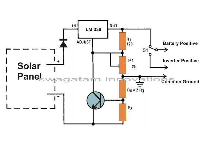
Solar panels are well-known devices that convert solar energy or sunlight into electricity. A solar panel consists of discrete sections of individual photovoltaic cells, each capable of generating a small amount of electrical power, typically between 1.5 to 3...
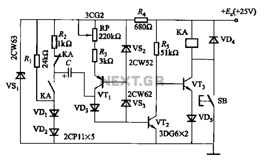
Charging time relay circuit 2 is a long delay circuit. When the capacitor C is 5000 µF, the delay can be up to 1.3 hours. Transistors VT1 and the VS2, VS3 group function as a constant current source to...
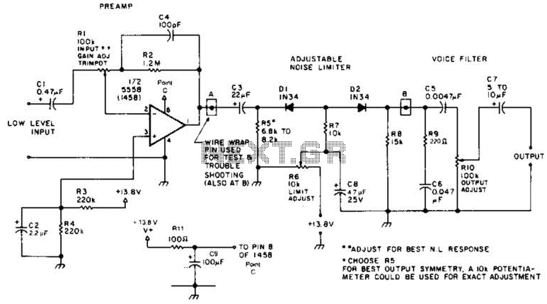
A preamplifier in the audio frequency range amplifies a noisy audio signal to drive a diode clipper. Suitable audio input levels would be in the 10-mV to 1-V range. The audio preamplifier circuit is designed to enhance weak audio signals, typically...
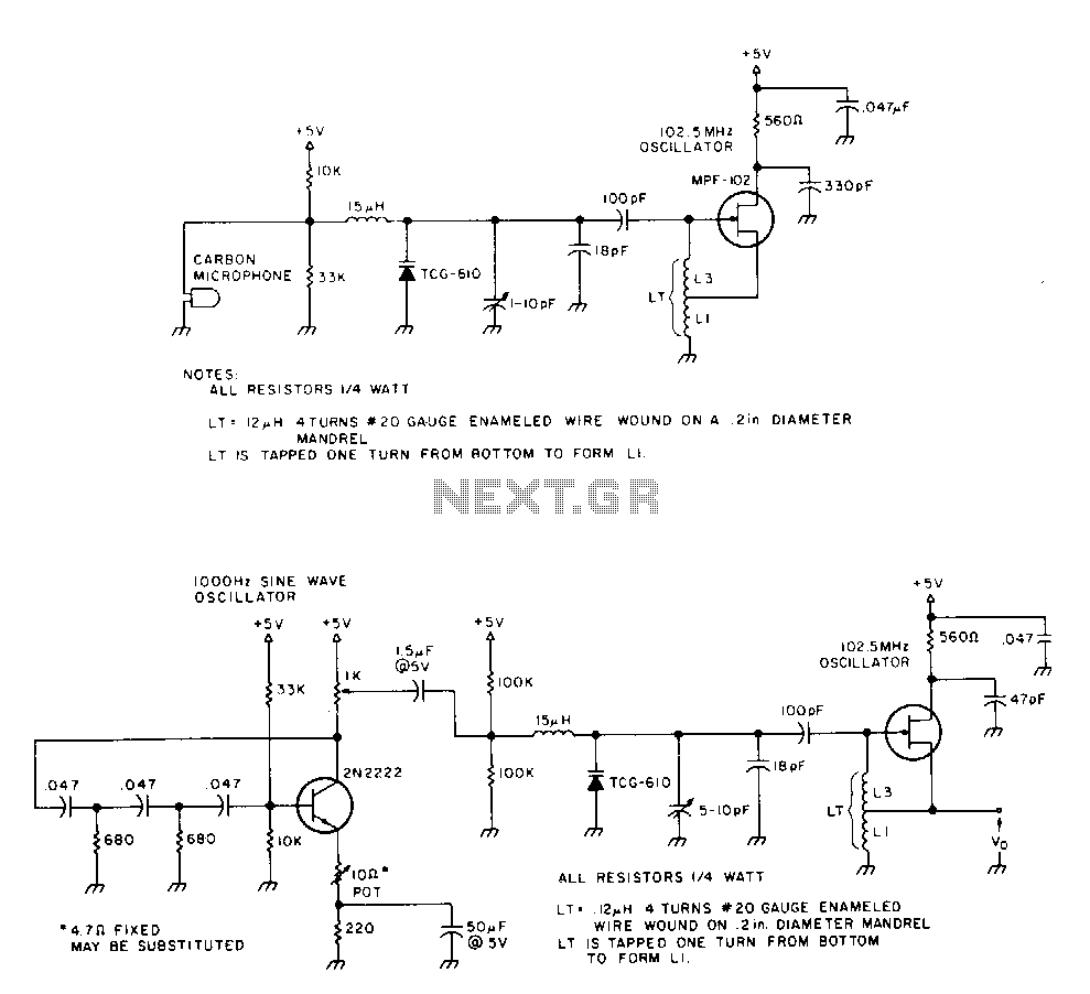
The 2N2222 circuitry is a three-element, phase-shift oscillator circuit designed to produce a 1,000 Hz sine wave. This sine wave is applied to the TCG-610 varactor diode, which has a capacitance of 6 pF at 4 V. This application...
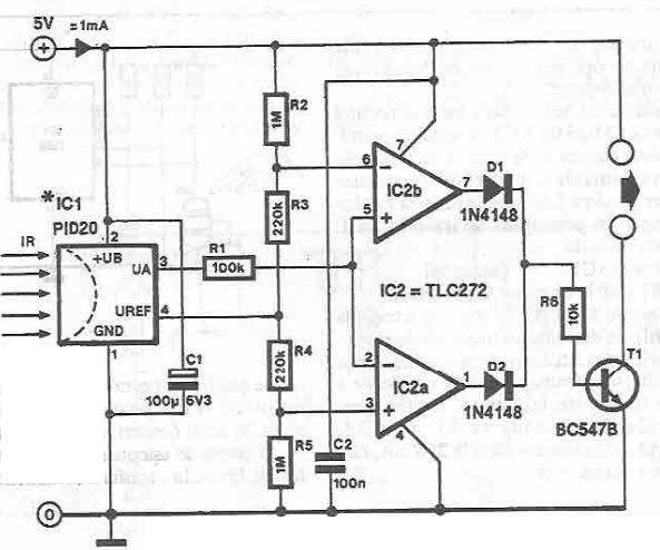
This infrared detector circuit is designed using the PID20 integrated circuit manufactured by Siemens, which converts thermal radiation into electrical impulses. It includes an operational amplifier and several electronic components. The output signal at pin 3 is compared with...
Figure 2-33 (a) illustrates the schematic diagram of a robot approaching an object. When no objects are detected in front of the robot, it moves forward in a straight line. If an object is detected on the left or...