
Simple Transformerless 5 Volt Power Supply
The described circuit represents a practical solution for low-power applications where space and component count are critical. The use of a JVR varistor provides essential protection against voltage surges, enhancing the reliability of the circuit. The integration of a simple voltage divider and transistor switching mechanism allows for effective management of power delivery, while the soft-start circuit mitigates inrush current, protecting sensitive components from damage during power-up. The adjustable potentiometer enables fine-tuning of the output current, ensuring that the circuit can accommodate varying load demands without excessive heat generation. The zener diode serves a dual purpose, providing voltage regulation and protecting the reservoir capacitor from potential overvoltage conditions. The overall design emphasizes efficiency and safety while addressing the challenges posed by low-power mains-powered devices. Proper precautions must be taken during assembly and operation to ensure user safety and circuit integrity.An increasing number of appliances draw a very small current from the power supply. If you need to design a mains powered device, you could generally choose between a linear and a switch-mode power supply. However, what if the appliance`s total power consumption is very small Transformer-based power supplies are bulky, while the switchers are gen
erally made to provide greater current output, with a significant increase in complexity, problems involving PCB layout and, inherently, reduced reliability. Is it possible to create a simple, minimum part-count mains (230 VAC primary) power supply, without transformers or coils, capable of delivering about 100 mA at, say, 5 V A general approach could be to employ a highly inefficient stabilizer that would rectify AC and, utilizing a zener diode to provide a 5.
1 V output, dissipate all the excess from 5. 1 V to (230G—v2) volts in a resistor. Even if the load would require only about 10 mA, the loss would be approximately 3 watts, so a significant heat dissipation would occur even for such a small power consumption. At 100 mA, the useless dissipation would go over 30 W, making this scheme completely unacceptable. Power conversion efficiency is not a major consideration here; instead, the basic problem is how to reduce heavy dissipation and protect the components from burning out.
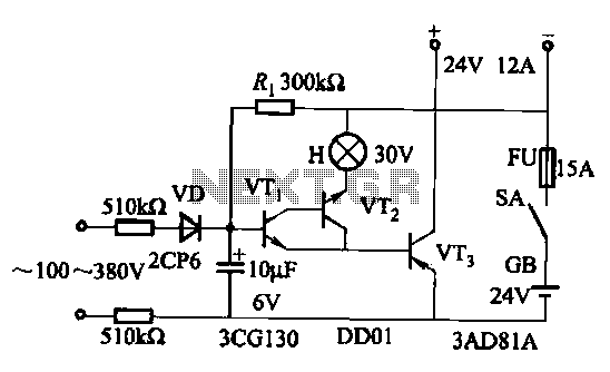
The circuit shown here is one of the simplest ways to achieve the above goals in practice. A JVR varistor is used for overvoltage/surge protection. Voltage divider R1-R2 follows the rectified 230 V and, when it is high enough, T1 turns on and T3 cannot conduct. When the rectified voltage drops, T1 turns off and T3 starts to conduct current into the reservoir capacitor C1.
The interception point (the moment when T1 turns off) is set by P1 (usually set to about 3k3), which controls the total output current capacity of the power supply: reducing P1 makes T1 react later, stopping T3 later, so more current is supplied, but with increased heat dissipation. Components T2, R3 and C2 form a typical soft start` circuit to reduce current spikes this is necessary in order to limit C1`s charging current when the power supply is initially turned on.
At a given setting of P1, the output current through R5 is constant. Thus, load R4 takes as much current as it requires, while the rest goes through a zener diode, D5. Knowing the maximum current drawn by the load allows adjusting P1 to such a value as to provide a total current through R5 just 5 to 6 mA over the maximum required by the load. In this way, unnecessary dissipation is much reduced, with zener stabilization function preserved. Zener diode D5 also protects C1 from over voltages, thus enabling te use of low-cost 16 V electrolytics.
The current flow through R5 and D5, even when the load is disconnected, prevents T3`s gate-source voltage from rising too much and causing damage to device. In addition, T1 need not be a high-voltage transistor, but its current gain should exceed 120 (e. g. BC546B, or even BC547C can be used). The circuit is not galvanically isolated from the mains. Touching any part of the circuit (or any circuitry it supplies power to) while in operation, is dangerous and can result in an electric shock!
This circuit should not be built or used by individuals without proper knowledge of mains voltage procedures. 🔗 External reference
Related Circuits
The most effective way to understand space-charge tubes is to examine actual circuits. Review the online circuits provided below, and check if any older print articles are available from friends or personal collections. After familiarizing yourself with the material,...
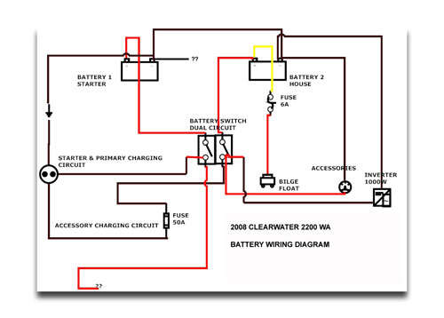
If the instruments have power when the key is turned on, the next step is to check the neutral safety switch. According to standard boat wiring colors, follow the yellow/red wire from the starter post on the key switch...
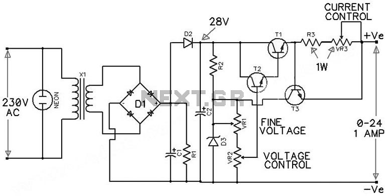
The circuit presented is an economical smooth variable power supply that provides an output range of 0V to 24V. It incorporates all necessary controls and short circuit protection while maintaining acceptable regulation and a ripple-free output, utilizing a minimal...
An AC-DC power supply without a power switching circuit is typically employed in lighting load circuits. When the power grid is restored, the standby power supply automatically switches on. The automatic switching circuit utilizes a transistor, as illustrated. The...
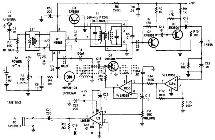
The integrated circuit Ul (an NE602 double-balanced mixer) functions as both an oscillator and a frequency mixer. Signals from the antenna input (at Jl) are transmitted through a DC-blocking capacitor C1 to the RF gain control, Rl, and subsequently...
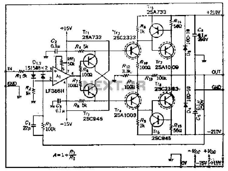
This amplifier circuit operates with an OP amplifier that is power-driven, which leads to the presence of floating voltage errors and necessitates a high-pressure booster for transistor protection. The circuit utilizes a mutual feedback configuration, connecting to the output...