
Automatic emergency light circuit
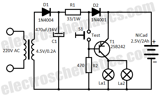
The automatic emergency lighting circuit is designed to provide illumination during unexpected power outages. The primary components of this circuit include a NiCad (Nickel-Cadmium) battery, a charging circuit, a lamp, and a control mechanism that detects power failure.
When the mains power is available, the circuit allows the NiCad battery to charge, ensuring that it remains ready for use. Typically, a diode is included in the charging path to prevent reverse current flow, which could discharge the battery when mains power is restored.
In the event of a power failure, the control mechanism, often implemented with a relay or a transistor, detects the loss of voltage and subsequently activates the lamp. The lamp can be an LED or an incandescent bulb, depending on the design requirements. The circuit must be configured to ensure that the lamp operates at the correct voltage and current levels, which may involve the use of a voltage regulator or a suitable driver circuit.
The emergency lighting circuit is designed to be energy-efficient, ensuring that the battery can provide adequate illumination for a reasonable duration. The choice of a NiCad battery is significant due to its ability to deliver high discharge rates and recharge efficiently, although considerations regarding battery life and environmental impact should also be acknowledged.
Overall, this circuit serves as a practical solution for maintaining visibility during power outages, enhancing safety and convenience in residential and commercial environments.This low cost automatic emergency lighting circuit turns on a lamp during power failures. It is powered by a NiCad battery that is being charged by the mai. 🔗 External reference
Related Circuits
There are two differing opinions regarding the charging of alkaline batteries. Some assert that charging is effective, while others caution against it due to the risk of explosion. It is acknowledged that rechargeable alkaline batteries can typically endure 30...
The Wireless Keylogger consists of two main building blocks: the transmitter and the receiver. The actual keylogging takes place in the transmitter, which is in fact a PS/2 hardware keylogger, with a built-in 2.4 GHz wireless module. Captured keystroke...
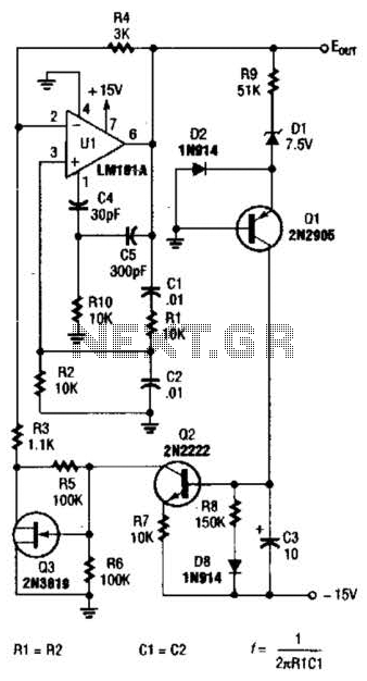
For variable-frequency operation, Rl and R2 can be replaced by a dual potentiometer. In electronic circuits that require variable-frequency operation, the use of a dual potentiometer as a replacement for resistors Rl and R2 can provide enhanced functionality and flexibility....

This simple LED light flasher project utilizes a Hex Inverter 74C04 integrated circuit (IC) to generate a square wave pulse, which is employed to alternately turn two LEDs on and off. The circuit design comprises a 74C04 Hex Inverter IC,...
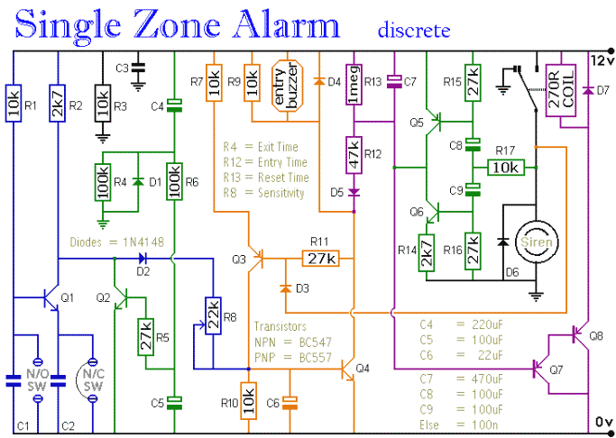
The circuit includes automatic entry and exit delays, a timed bell cut-off, and a system reset feature. It accommodates both normally open and normally closed switches, making it compatible with common input devices such as pressure mats, magnetic reed...
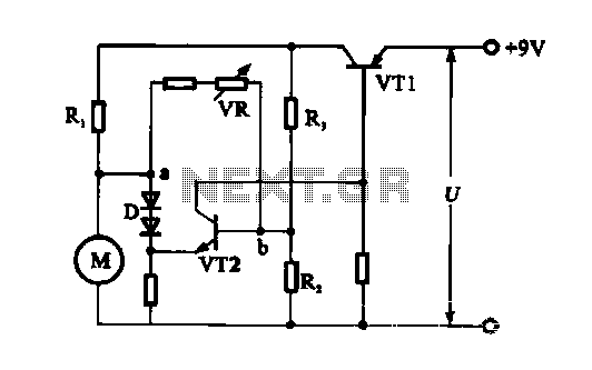
The electronic circuit for steady speed motor applications utilizes an automatic remote control system to regulate the motor power supply, thereby achieving consistent speed control. The circuit diagram illustrates a DC motor connected to the system. Given that the...