
Simple Two Way Communication Intercom Circuit Schematic diagram
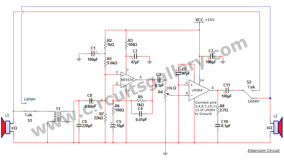
The intercom circuit operates on a dual-channel basis, allowing users to communicate in both directions. The core components include the LM384 and NE5534 integrated circuits, which are critical for audio processing. The LM384, known for its ability to deliver significant audio power, is ideal for driving loudspeakers in intercom applications. Its output power capability, combined with a 15-volt power supply, ensures that the audio signal remains strong and clear.
The NE5534 preamplifier plays a vital role by boosting the audio signal before it reaches the LM384. This preamplification is crucial for maintaining audio fidelity, especially in environments with background noise. The gain setting of 11 for the LM384 ensures that the output signal is sufficiently amplified for clear communication.
The use of switches S1 and S2 allows for seamless toggling between talking and listening modes. This design enables each loudspeaker to function as both a microphone and a speaker, depending on the switch configuration. The ability to add more speakers enhances the system's versatility, making it suitable for various applications, from small residential setups to larger office environments.
Overall, the intercom circuit is a straightforward yet effective solution for two-way communication, leveraging the capabilities of the LM384 and NE5534 to deliver reliable audio performance. The design simplicity and scalability make it an attractive option for users seeking an efficient intercom system.Intercom or Inter communication circuit is a two directional communication system. It provides a reliable communication line and is extremely easy to implement. The circuit is prepared by an amplifier, two switches and two loudspeakers. We can extend this circuit by adding more number of speakers with the help of switches. IC LM384 works as a powe r output amplifier in this intercom circuit. LM384 provides almost 2 watts of audio power via 15 volts supply voltage. This intercom circuit diagram is very simple and practical circuit capable of using intercoms for homes, office intercom. If switch S1 is in Talk` contact, L1 functions as a Microphone. If it is in Listen` position, L1 functions as a Speaker. (Similar case applicable in L2 also. ) IC NE5534 works as a Pre Amplifier which boosts the Audio signal before applying to the LM384 amplifier section.
The gain of the LM384 op amp amplifier is set to 11. By changing the switch positions of S2 in to Talk` position and S1 to Listen` position, L2 get connected to the input section and L1 connected to output section. 🔗 External reference
Related Circuits
Most peripherals that interface with a PC utilize a USB port. The computer's power supply circuit, specifically the switched-mode power supply (SMPS), is designed to provide constant power to all internal components. However, when external peripherals that require a...
Long-distance infrared transmitter circuit diagram. This simple circuit offers a considerable range by utilizing three infrared transmitting LEDs (IR1 through IR3) in series to enhance the radiated power. To further improve directivity and power density, the IR LEDs can...
This is basically a high gain amplifier with feedback that causes the LED to flash at a rate determined by the 10u and 330k resistor. Remove one of the transistors and insert the unknown transistor. When it is NPN...
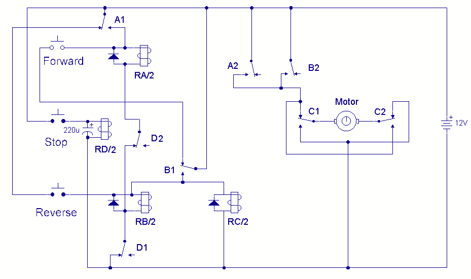
A DC motor reversing circuit using non-latching push button switches. Relays control forward, stop, and reverse action, and the motor cannot be switched from forward to reverse unless the stop switch is pressed first. The described circuit employs a system...
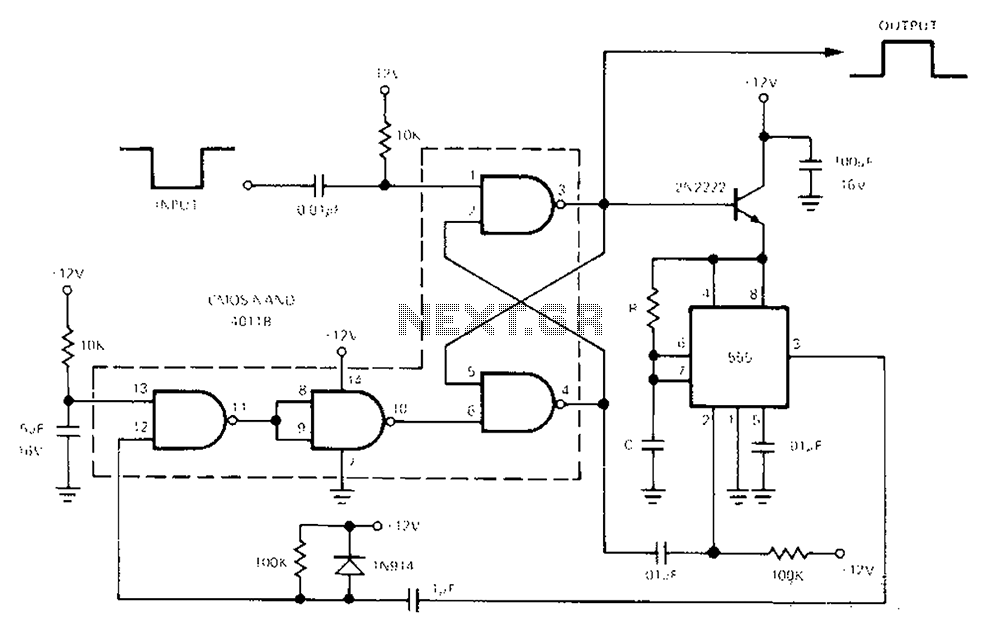
The 555 Timer facilitates a low-loss single-shot circuit and interfaces with the CMOS4011B NAND gate circuit. The standby power consumption is less than 50 µA. When the one-shot circuit is activated, the current consumption is 4.5 mA, and the...
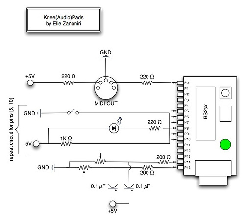
A few nice MIDI controller interfaces were discovered. The Knee(Audio)Pads are a wearable MIDI device. The MIDI controller interfaces mentioned provide innovative solutions for music production and performance. The Knee(Audio)Pads, in particular, represent a unique advancement in wearable MIDI technology....