
Simple Voltage comparator using CA3140
This circuit operates as a voltage window comparator, utilizing the CA3140 operational amplifier to monitor the input voltage against two adjustable thresholds, V1 and V2. The adjustable limits allow for flexibility in application, particularly in scenarios such as battery monitoring, where overcharging or undercharging conditions need to be identified. The choice of the CA3140 is significant due to its superior characteristics, which include low offset voltage and the ability to drive outputs close to ground level, thereby enhancing the circuit's sensitivity and responsiveness.
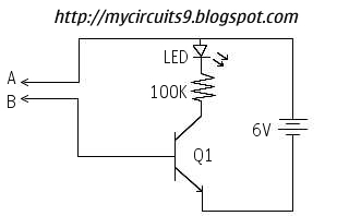
To set the thresholds, a potentiometer can be used to adjust V1 and V2, allowing users to define the acceptable voltage range for their specific application. The operational amplifier's output is connected to an LED indicator, which provides a visual cue when the input voltage is outside the defined limits. The inclusion of two 1N4148 diodes at the output ensures that the LED only activates when both conditions are met — either when the voltage exceeds V1 or falls below V2, effectively creating an AND gate logic.
The input stage of the circuit employs a voltage divider formed by two 10kΩ resistors, which helps to scale down the input voltage to a level suitable for the operational amplifier's input range. This configuration protects the operational amplifier from potential over-voltage conditions while allowing it to accurately respond to voltage variations. The output from the CA3140 is designed to drive the LED directly, providing immediate feedback to the user regarding the battery's status.
In summary, this circuit is a practical solution for monitoring battery voltage levels, with easy adjustments for various applications, leveraging the precision and reliability of the CA3140 operational amplifier.This circuit is a circuit diagram indicates when the input voltage differs from two defined limits, V1 and V2. The limits that can be adjusted and the circuit is designed to trigger the adjustable window . Supply voltage, Vcc must be higher than the highest input voltage by at least 2 volts. One application here is to monitor a 12V car battery. V1 can be set to 14V and V2 to 11V thus giving an indication of more than the cost or weak batteries. Op-amp used here is the CA3140 MOSFET. They are used to advantage because they have less output offset voltage and can switch to 0volts close.
If any other use op-amps like the LF351 or CA741 will need to have an offset null control. This is just a 10k preset reached between pins 1 and 5, the wiper connected to the negative supply op-amps or 4 pins. The following is a schematic drawing: With this circuit the op-amp will turn on the LED if the input voltage out of limits, the two 1N4148 diodes to form an AND -gate at the output.
Input voltage to be monitored are fed through a series of 10k resistors on the input of both op-amps. If the input voltage is greater than the limit set by V1 it will CA3140 output swing to almost full supply voltage and LED lights.
Similarly, if the input voltage is less than the limit set by V2 the op-amp will swing to the Vcc and the LED light. 🔗 External reference
Related Circuits
A function generator that operates within a frequency range of 0.1 Hz to 20 MHz can be easily constructed using the MAX038 integrated circuit chip. This describes a straightforward implementation of the device. The MAX038 is a precision waveform generator...
This is a straightforward water level buzzer circuit designed to detect the water level in tanks, pools, washing machines, and similar applications. The circuit features two probes that, upon contact with water, trigger the buzzer to emit a sound....
Power an RS232-TTL converter circuit using the serial port to eliminate the need for an external power supply. It has been noted that the DTR, RTS, and TD pins can facilitate this. Since the TD pin is already utilized...
Create a USB to Serial Converter using the ATmega8 microcontroller. The firmware source code for the ATmega8 is available for free download. Since the ATmega8 does not natively support USB communication, the USB communication protocol must be implemented within...
All naturally occurring phenomena such as sound, temperature, and pressure are analog in nature. To enable a microcontroller to read analog signals for the analog-to-digital conversion process using a built-in analog-to-digital converter (ADC), it is essential to condition the...
This circuit offers an advantage over traditional continuity testing devices, which typically utilize a multimeter to assess circuit continuity. Multimeters are not suitable for testing high impedance or resistance circuits, such as transformers, capacitors, and high-value resistors. This circuit...
Warning: include(partials/cookie-banner.php): Failed to open stream: Permission denied in /var/www/html/nextgr/view-circuit.php on line 713
Warning: include(): Failed opening 'partials/cookie-banner.php' for inclusion (include_path='.:/usr/share/php') in /var/www/html/nextgr/view-circuit.php on line 713