
microcontroller 16f707 capacitive touch button

The capacitive sensing system described integrates a Microchip CSM module, which serves as the core for various sensing applications. The CSM module's architecture allows for the implementation of capacitive touch sensing without mechanical components, making it suitable for modern user interfaces. The oscillator's triangular waveform is critical for determining capacitance changes, as it provides a clear signal that can be analyzed for fluctuations in capacitance resulting from external influences, such as proximity or touch.
The design considerations for this application include the selection of appropriate reference voltages and the configuration of the timers to ensure accurate frequency measurement. The integration of a DAC and FVR enhances the precision of the measurements, allowing for applications that require high sensitivity. The choice of using a 16-bit timer, such as Timer1, facilitates the counting of oscillations over longer periods, which is beneficial for applications where minor capacitance changes need to be detected.
Overall, the capacitive sensing system described offers a versatile solution for a wide range of applications, from simple touch interfaces to complex sensor systems capable of measuring minute capacitance changes. The comprehensive guide provided serves as a valuable resource for engineers and developers looking to implement capacitive sensing in their projects, offering insights into both hardware configuration and software implementation.there are countless applications for use of this hardware. Touch pad, proximity sensors, readout of capacitive sensors, extreme precision capacitance measurement, ultra small capacitance change detection, soil moisture, skin moisture measurement are just some of them. But then I started to search for examples and I was surprised because there wasn` t any! At least not ones that was helpfull. That is why I made this complete guide for capacitive sensing using excellent Microchip CSM module inside some of them microcontrollers. The CSM simplifies the amount of hardware and software setup needed for capacitive sensing applications.
Only the sensing pads on the Printed Circuit Board (PCB) need to be added. The capacitive sensing modules allow for an interaction with an end user without a mechanical interface. The capacitive sensing oscillator consists of a constant current source and a constant current sink, to produce a triangle waveform.
On picture below you can see typical waveform recorded ad one of the touch pads while measured with Microchip CSM module. To explain it simply upper current source feeds current into analog pin capacitance until voltage reaches Ref+.
Then upper current source shuts down and lower current source engages. He sinks current from analog pin capacitance until voltage reaches Ref- and it all goes in circle. This is why we call it oscillator. Since it is constant current voltage is changing linearly which we can see on picture above. The oscillator is designed to drive a capacitive load (single PCB pad) and at the same time, be a clock source to one of the timers. Cap Sense Oscillator A can be input of Timer1 and TimerA depending on configuration we make. I personally prefer Timer1 since it is 16 bit timer and it is easier to count bigger number of oscillations with it.
Current settings are divided into two groups. Low range that use internal reference voltages. This means you cannot change upper and lower voltage threshold in CSM oscillator. For touch screen purposes and when you do not need to know amount of capacitance you are reading this is ok. High range If you want to use this module as extra precise small capacitance meter that can measure capacitance order or ~fF (that is FEMTOFARAD!
~10 E-15) then it is easier to do calculations when you can set precise voltage thresholds. Current source range group is selected by setting CPSxRM configuration bit When using high range currents beside usual setup you must enable and properly configure FVR (Fixed voltage reference) and integrated peripheral DAC Digital-to-analog convertor that is also placed inside this chip. As you can see it is easier to use low range currents but I prefer to use high current range because it gives you better control and readout stability when measuring capacity.
The capacitive sensing oscillator will continue to run as long as the module is enabled, independent of the part being in Sleep. In order for the software to determine if a frequency change has occurred, the part must be awake. However, the part does not have to be awake when the timer resource is acquiring counts. When you configure all settings and you have your CSM module running you still need to measure CSM oscillator frequency.
To measure the frequency of the capacitive sensing oscillator, a fixed time base is required. Any timer resource or software loop can be used to establish the fixed time base. It is up to the end user to determine the method in which the fixed time base is generated. The fixed time base cannot be generated by the timer resource that the capacitive sensing oscillator is clocking. For our example Timer1 is dedicated to CSM module and therefore cannot be used for fixed time base measurement.
Let us make checklist of things you need to do to measure capacitance of CPSA module pin. In this example we will use Timer1 for counting CPSA module CSM oscillator. For measuring its frequency we will use fixed time base created by Timer3. We will make check list for using high range current with Ref- voltage from DAC module which is more complex. 6. Configure Timer1 as normal timer operation. Only difference is that now its clock comes from CSM module instead of system clock. Set its Interrupt, prescaler, Disable External Clock Input Synchronization and Gate operation, Turn it on.
8. Enable DAC, Set its reference voltage to FVR and make its output value. Notice this value will be used as Ref- Voltage in CSM oscillator. In this case positive voltage reference in this oscillator REF+ will be FVR value. 9. Enable some of remaining timers to measure fixed time period in which you will read how many oscillations from CSM oscillator Timer1 has counted. For example enable Timer3 to work and enable its interrupt. If you are wondering how to make hardware implementation of Touch button to read capacity from it, it is very simple.
Since this module is very sensitive any shape and size will do. Best is to make it size of top of human finger (2cmx2cm). You experiment and you will see what get you best results. I also made project and tested CSM function in practise. My ruff calculations are that when i aproach with finger to capacitive pad on pcb i change capacity for about 25fF! and it is not problem to detect with this module. It would be too long to explain all in details here but if you are interested to work with it or you have questions P.
M. me or see this full guide with more details at and for you to start working with mTouch i privided full C source code and project for download with full detailed explanations and video presentation of its work at 🔗 External reference
Related Circuits
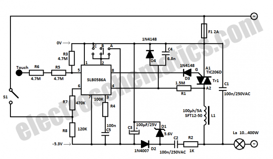
The SLB0586A integrated circuit from Siemens can be utilized to construct a straightforward touch light dimmer circuit, enabling the user to modify the intensity of a lamp. This circuit also incorporates a TIC206D component. The SLB0586A is a specialized touch-sensitive...
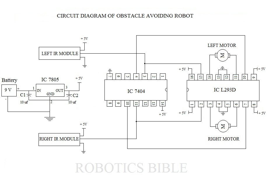
An obstacle-avoiding robot is an intelligent device that can automatically sense and navigate around obstacles in its path. It is designed without a microcontroller to simplify the circuitry and programming requirements. Understanding the circuit diagram is essential for constructing...
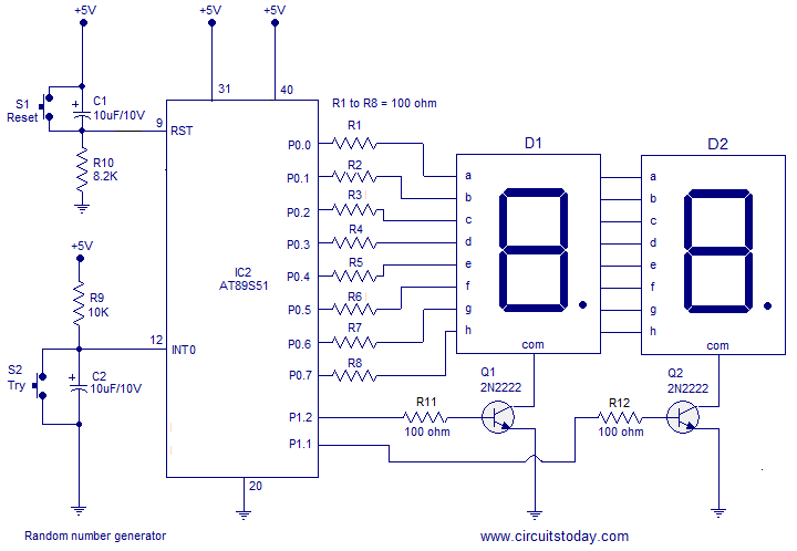
A simple random number generator utilizing the 8051 microcontroller. The AT89S51 is the controller employed in this setup. The circuit design for the random number generator based on the AT89S51 microcontroller involves several essential components and connections. The AT89S51 microcontroller,...
The project was originally intended as a present for my brothers dorm room, but a bad capacitor and the lack of a proper oscilloscope caused delays. It has not made it off the breadboard, and it probably will not...

An NPN bipolar transistor is typically utilized for relay switching, particularly with 12V coil-rated relays, as it helps maintain circuit separation. A diode is also added to prevent issues. The necessity of driving the relay with a transistor depends...
Just the solution for AVR applications in which I/O is tight, such as the ATtiny12. This should work well on other kinds of controllers that have independently controlled I/O direction registers, such as PIC and 6805 controllers. This solution...