
Simplified Long-Distance Call LockCircuit
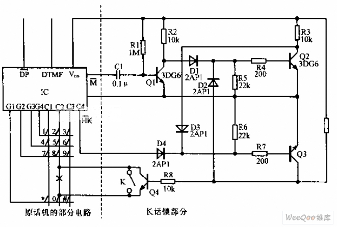
The long-distance call lock circuit is an essential tool for managing telecommunication expenses, particularly in environments where unauthorized long-distance calls may occur. The circuit typically incorporates a relay or a transistor switch that is controlled by the position of switch K.
When switch K is in the designated position, it engages a blocking mechanism that interrupts the dialing process for long-distance calls. The circuit is designed to detect the dialing of the number '0', which is often the prefix for long-distance calls in many telecommunication systems. The blocking mechanism can be implemented using a combination of resistors, capacitors, and diodes that work together to create a control signal to the relay or transistor.
The power consumption of the circuit is a critical consideration, as it must be low enough to avoid excessive energy costs while still providing reliable operation. The compatibility of the device with various telephone systems is facilitated through the use of standard components that can be easily integrated into existing phone lines without requiring significant modifications.
In summary, this long-distance call lock circuit effectively prevents unauthorized long-distance dialing while preserving the basic functionality of the telephone system, making it a valuable addition to any telecommunication setup.Simplified long-distance call lock is shown in the above picture. The lock can lock out the long-distance call without affecting the original function. It ispower-consuming, but it has very good compatibility. If switch K is placed as the picture shows, first dial the number 0,, and you ll find the 0 can not be dialed and the long-distance call can not.. 🔗 External reference
Related Circuits
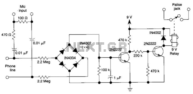
The DC voltage on a telephone line typically ranges from 45 to 50 V when on-hook and drops to around 6 V when off-hook. This circuit utilizes the voltage drop to activate a relay, which in turn controls a...
The system utilizes the DSP56F826 chip as the primary control module and incorporates a CMOS digital image sensor capable of capturing images with a resolution of 640 x 480 pixels. For applications requiring higher resolution, a chip supporting 1024...
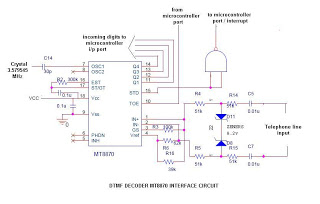
This is a straightforward circuit utilizing the DTMF decoder MT8870 (or CM8870). As illustrated in the circuit, an interrupt will be generated (if the NAND output is connected to the INT of the microcontroller) whenever a call is received...
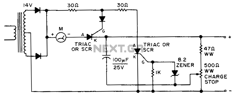
By adjusting the circuit with a 500-ohm resistor, the resistor is integrated into a fully charged battery system. The circuit described involves a 500-ohm resistor that plays a crucial role in regulating the operation of a fully charged battery system....

This circuit utilizes a simple calculator along with a chip-on-board (COB) from an analog quartz clock to create a telephone call meter. The calculator converts STD/ISD calls into local call equivalents and continuously displays the current local call meter...
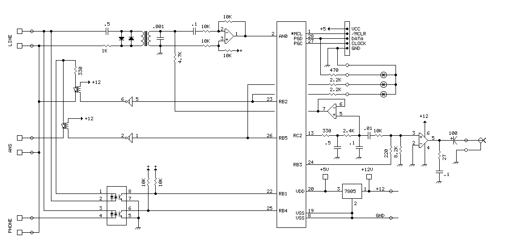
The PIC16F870 chosen for this project has several analog channels. One of these is used to capture the DTMF tones and decode the digits. The actual phone connections are made using a 'hacked' 5 line expander from Radio Shack....
Warning: include(partials/cookie-banner.php): Failed to open stream: Permission denied in /var/www/html/nextgr/view-circuit.php on line 713
Warning: include(): Failed opening 'partials/cookie-banner.php' for inclusion (include_path='.:/usr/share/php') in /var/www/html/nextgr/view-circuit.php on line 713