
simplify MCU circuit design
The debugger features three important tabs located in the top-left corner that dictate the view of the source. Selecting the Flowchart tab provides access to the flowchart for debugging purposes. The Flowchart+Code tab displays both the flowchart and the corresponding assembly code, allowing the user to place breakpoints in either view. The final mode, Code, enables traditional debugging of assembly language. To enhance synchronization between the flowchart and assembly code, TINA automatically inserts additional labels and comments, improving code readability. Breakpoints can be utilized to pause code execution at specified points, facilitating the examination of registers and parameters. TINA provides various methods for inserting and removing these breakpoints. A notable feature of TINA's flowchart programming is the capability to test and debug circuit operation, including MCUs programmed via flowchart, in a mixed analog-digital environment. A motor controller circuit included in TINA serves as an example that can be executed and debugged in the interactive mode of TINA.
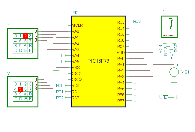
The PIC16F73 microcontroller is a versatile component that supports various input and output operations, making it suitable for tasks such as adding two numbers. The flowchart interface allows for intuitive programming; users can visually represent the logic of their application without needing to write complex assembly code directly. Each block in the flowchart corresponds to specific instructions or operations that the MCU will execute.
The TINA debugger enhances the development process by providing real-time feedback and debugging capabilities. By allowing users to set breakpoints, it enables an in-depth analysis of the program's execution flow. This feature is particularly beneficial during the development phase, as it helps identify and rectify issues in the code efficiently.
The ability to run and debug in a mixed environment is crucial for applications that require both analog and digital signals. The motor controller circuit serves as an excellent demonstration of this capability, allowing designers to simulate real-world conditions and assess the performance of their designs before physical implementation. By leveraging TINA's tools, engineers can significantly reduce development time and improve the reliability of their electronic designs.Writing MCU assembly code is often a hard and tedious task. You can simplify software development and gain more time to design the electronics hardware if, instead of manual coding, you use TINA`s Flowchart editor and debugger to generate and debug the MCU code, using just symbols and flow control lines, and then run or debug this code in digitalor mixed circuit environment. In the following example, a flowchart to controls a MCU embedded in a simple circuit. The flowchart adds two numbers that are read from two ports of the PIC16F73 microcontroller. There are three important tabs at the top-left corner of the debugger that establish the view of the source. If you select the Flowchart tab, you can see and debug via the Flowchart. If you select the Flowchart+Code tab, TINA will display both the flowchart and the assembly code. You can, in this view, place breakpoints both in the flowchart and in the assembly code. If you select the last mode, Code, you can debug using traditional assembly language debugging. Note that in order to synchronize the flowchart and the assembly code, and to make the code more readable, TINA inserts additional labels and comments into the code; for example: Breakpoints are used to halt code execution at user-specified points, permitting the examination of registers and parameters.
TINA offers several ways to insert and remove breakpoints. One of the most useful feature of TINA`s flowchart programming is that you can test debug circuit operation including MCUs programmed by flowchart, in mixed analog-digital environment. The following circuit, included in TINA, is a motor controller which you can run and debug in the interactive mode of TINA.
🔗 External reference
Related Circuits
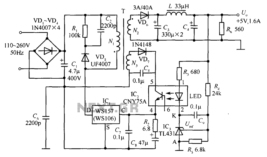
The circuit incorporates an optical coupler (CNY75A) and an adjustable precision shunt regulator (TL431). It includes current limiting resistors R3, R4, and R5 for the sampling resistor. As the output voltage (Uo) varies, the voltage across the sampling resistor...
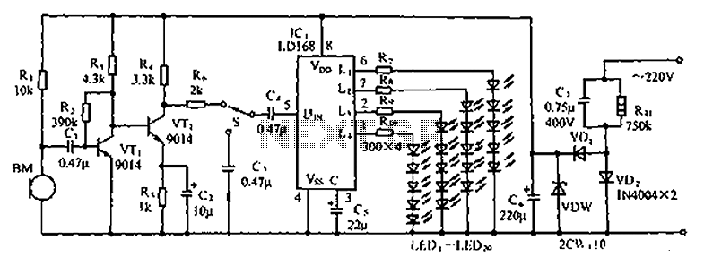
The circuit depicted in the figure involves the LD168, which functions as a sound level indicator for tape recorder speakers. It features four outputs capable of directly driving multiple light-emitting diodes. Additionally, the device can be activated by a...
Very often when enjoying music or watching TV at high audio level, we may not be able to hear a telephone ring and thus miss an important incoming phone call. To overcome this situation, the circuit presented here can...
This scan is from an old ETI Circuits #2 publication from the 1970s. It contains valuable operational amplifier information that is highly useful. With some knowledge, the six circuits presented serve as an instant reference, enabling various applications. These...
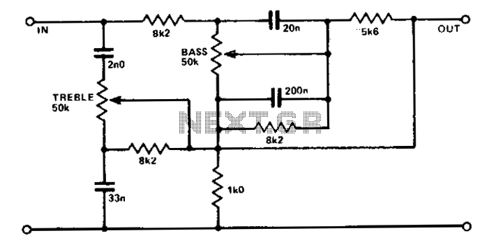
A simple circuit using two potentiometers and easily available standard value components provides tone control. The impedance level is suitable for low-level transistor or op-amp circuitry. This tone control circuit typically employs two potentiometers to adjust the bass and treble...
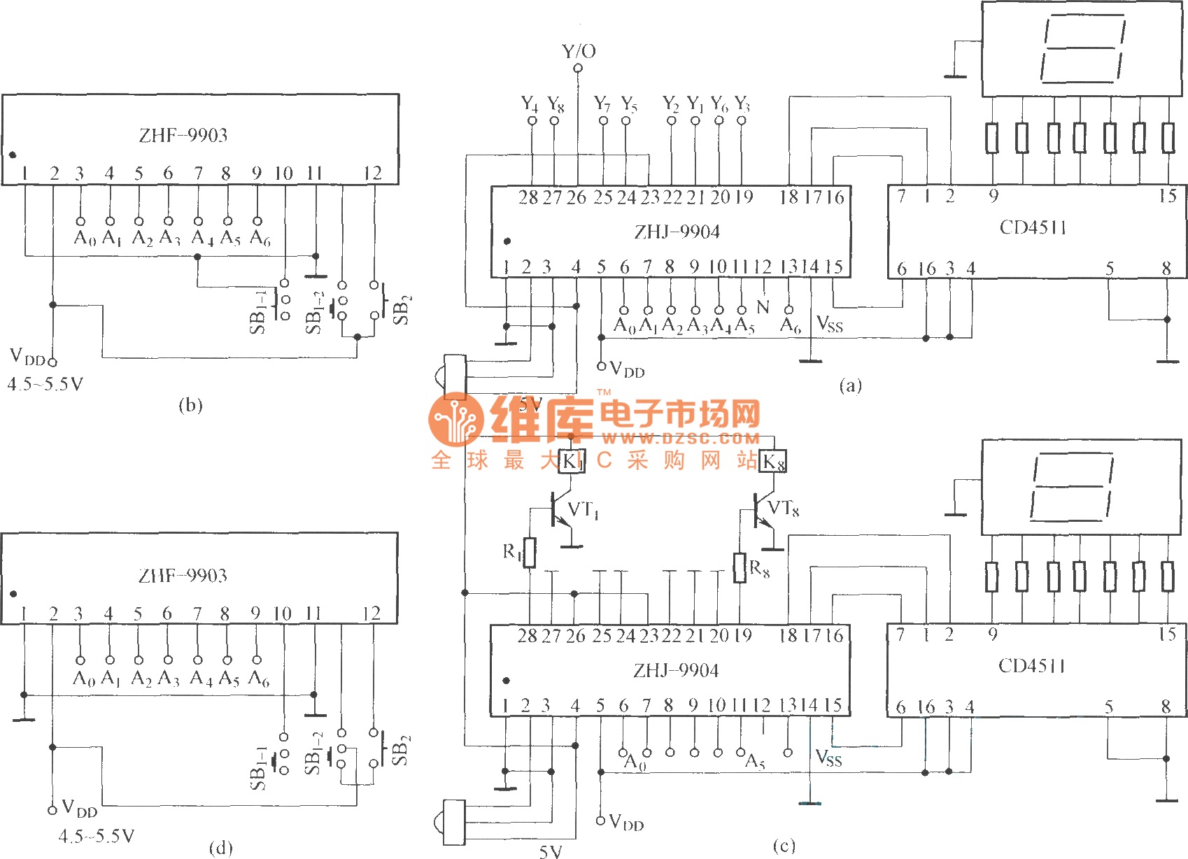
This is an eight-way signal remote control selection circuit composed of ZHJ-9904. It includes a remote control transmitter circuit, an eight-way switch control circuit, and a remote control transmitter. The eight-way signal remote control selection circuit utilizing the ZHJ-9904 is...
Warning: include(partials/cookie-banner.php): Failed to open stream: Permission denied in /var/www/html/nextgr/view-circuit.php on line 713
Warning: include(): Failed opening 'partials/cookie-banner.php' for inclusion (include_path='.:/usr/share/php') in /var/www/html/nextgr/view-circuit.php on line 713