
simulation Understanding a high voltage generator circuit
The high voltage DC converter circuit typically employs a transformer-based design to step up the voltage from a lower input level to a higher output level, suitable for applications such as powering Geiger tubes. The circuit generally consists of a switching transistor, a transformer, rectifying diodes, and filtering capacitors.
In this particular case, the use of an equivalent transistor to the 2N4403 may have implications on the switching characteristics of the circuit. The 2N4403 is a general-purpose NPN transistor, and its specifications, such as maximum collector current and switching speed, are critical in determining how effectively it can drive the transformer. If the replacement transistor has different parameters, it may not operate in the desired saturation region, leading to insufficient voltage gain.
The transformer plays a crucial role in stepping up the voltage. The turns ratio of the transformer defines how much the voltage will be increased. If the primary and secondary windings are not properly configured or if there is a mismatch in the winding ratios, the output voltage may not reach the expected levels. Additionally, the orientation of the windings can affect the phase relationship between the input and output, which could lead to reduced efficiency or failure to achieve the desired output.
The selection of diodes is equally important. Diodes are used to rectify the AC voltage generated in the secondary winding of the transformer. If diodes with a lower reverse voltage rating or higher forward voltage drop are used, they may not adequately handle the voltage generated, resulting in a lower output voltage. Furthermore, the recovery time of the diodes can affect the performance of the circuit, particularly at higher frequencies, as slow diodes may not switch off quickly enough, leading to power loss and reduced efficiency.
To troubleshoot the simulation, it would be prudent to verify the specifications of the components used, particularly the transistor and diodes, and ensure they are compatible with the circuit's design requirements. Additionally, examining the transformer turns ratio and ensuring proper winding orientation may help in achieving the expected output voltage. Understanding these factors will provide insight into the circuit's operation and assist in resolving the simulation discrepancies.A high voltage power supply 3V to 500V DC converter and someone suggested a circuit from techlib H. V. generator for Geiger tubes : However, when I tried to simulate it didn`t work, the output is nearly 9V, as the input. In the schematic I drew, the only difference with the proposed circuit is that I used an equivalent of 2N4403 transistor and different diodes.
I also tried reversing one of the winding connections but nothing changed. Could someone explain how this circuit works and how the output is affected by the selection of the diodes Maybe that will also help me understand what`s going wrong with the simulation. 🔗 External reference
Related Circuits
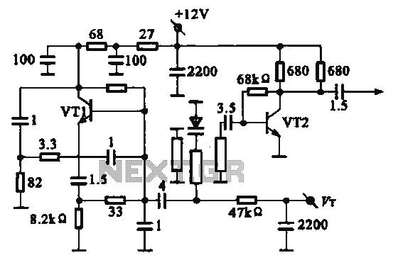
The local oscillator operates at frequencies of 1 GHz or higher, utilizing a common collector circuit, which makes it challenging to generate low-frequency self-oscillation. Typically, the local oscillator signal is passed through a buffer amplifier stage before being applied...
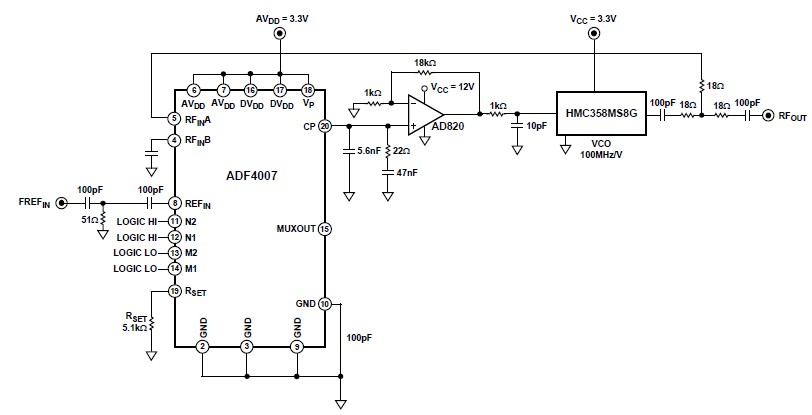
The ADF4007 high-frequency divider Phase-Locked Loop (PLL) synthesizer can be utilized in a variety of communication applications. It operates up to 7.5 GHz on the RF side and 120 MHz at the Phase Frequency Detector (PFD). The device includes...
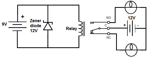
This project involves the construction of a relay driver suitable for both DC and AC relays. Since DC and AC voltages operate differently, the setups for their respective relay drivers require slight variations. A generic relay driver that can...
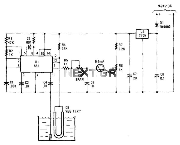
Using a capacitor sensor to detect water levels is a straightforward sensing method. This circuit employs C5, which consists of 10 to 20 inches of #22 enameled wire as one of the electrodes. The oscillator, an NE556 timer, experiences...
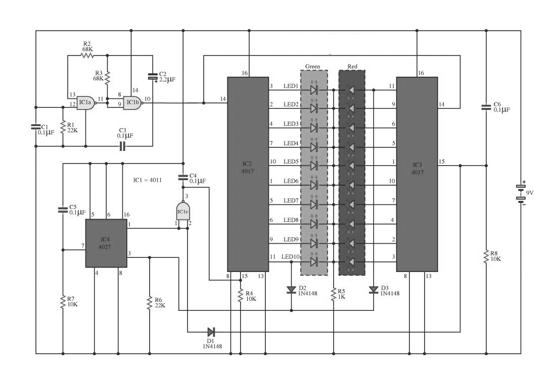
This circuit operates on alternating two colors using a 2-color LED with a built-in 3-pin configuration. It alternates the glow of each LED until the base, switching between two colors. The circuit comprises a NAND gate IC, two 10-counter...
Constantly changing light and sound analog controller circuit 04 The circuit designated as the "Constantly Changing Light and Sound Analog Controller Circuit 04" is designed to modulate both light and sound outputs in a dynamic manner. This type of...