
Water-Level Measurement Circuit
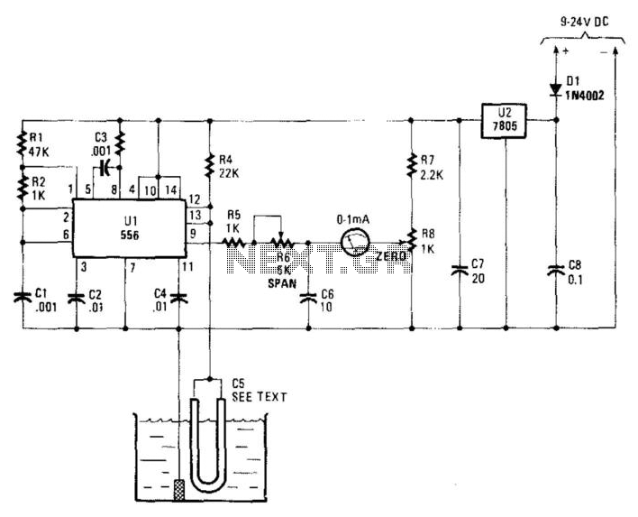
The water level detection circuit operates on the principle of capacitance variation with changing water levels. The NE556 timer is configured in an astable mode, generating a square wave output whose frequency is influenced by the capacitance of the sensor, represented by C5. As the water level rises or falls, the dielectric constant around the wire electrode changes, thus altering the capacitance.
To implement this circuit, the 10 to 20 inches of #22 enameled wire is coiled or arranged in such a way that it can effectively sense the water level. This wire acts as one plate of a capacitor, with the water serving as the dielectric medium and the surrounding environment as the other plate.
The output frequency from the NE556 timer is monitored at pin 9, which can be connected to a frequency counter or a simple analog meter. The meter provides a visual indication of the water level based on the frequency shift. The frequency output can be calibrated to correspond to specific water levels, allowing for precise monitoring.
Adjusting the length or configuration of C5 can optimize the sensitivity and response time of the sensor, making it adaptable for various applications, such as in tanks, wells, or other water storage systems. Proper calibration and testing are essential to ensure accurate readings and reliable performance in the desired environment. Using a capacitor sensor to detect a water level is a simple method of sensing. This circuit uses C5, which is 10" to 20" of #22 enamelled wire as one electrode. This shifts the oscillator, an NE556 timer, in frequency. The frequency shift depends on the capacitance change, which in turn varies with water level. A meter connected to pin 9 of the 556 is used as an indicator. C5 can be made larger or smaller to suit the intended application. 🔗 External reference
Related Circuits
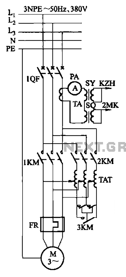
Autotransformer voltage starting, with an adjustable starting time of 30-60 seconds. It includes the SDJ electrode liquid level sensor of HJ-13 type, a pump control system box of HKD-21B type, 1MK level modules adopted by HKG-1SG type, 2MK start...
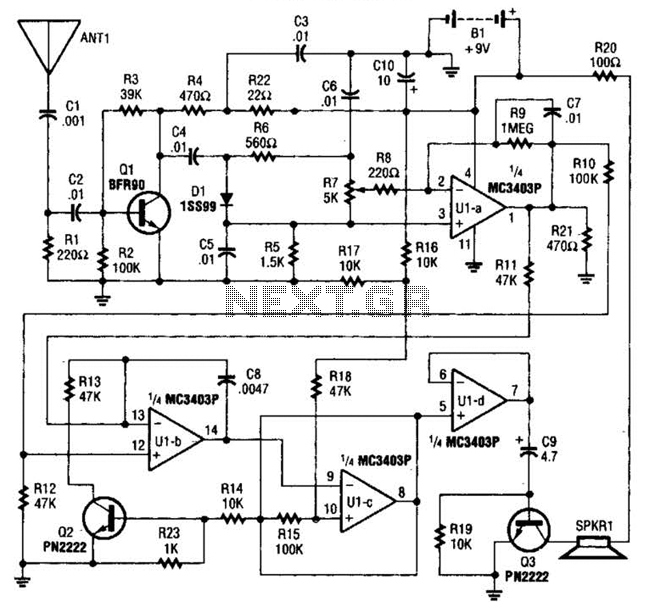
The circuit is constructed around a single integrated circuit (U1), specifically an MC3403P quad op-amp, three transistors (Q1-Q3), and several supporting components. It receives its input from the antenna (ANT1). The signal is processed through a high-pass filter composed...
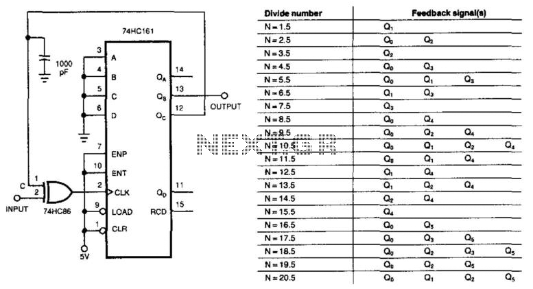
This circuit divides the input signal by +1/2 instead of dividing by an integer. With the feedback connections as illustrated in the figure, the circuit effectively divides by 3.5. Point C ultimately determines when the input triggers the 74HC161...
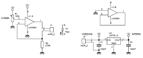
This led tester uses a power switched op-amp. The control range is about 0-30mA. Thus, all test and standard LEDs, the voltage across the LED to read. The power supply is an example lab power supply at least 15V,...

This circuit generates a siren sound when switch S1 is pressed. The sound frequency increases as capacitor C1 charges, and when switch S1 is released, the frequency decreases as capacitor C1 discharges. The circuit operates on a simple principle of...
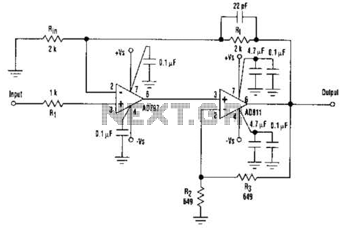
An ultra-low-noise, low-distortion operational amplifier, the AD797, is combined with the ADS 11 operational amplifier, which provides high bandwidth and a 100-mA output drive capability. This composite amplifier circuit is effective for driving high-resolution ADCs and ATE systems. The...
Warning: include(partials/cookie-banner.php): Failed to open stream: Permission denied in /var/www/html/nextgr/view-circuit.php on line 713
Warning: include(): Failed opening 'partials/cookie-banner.php' for inclusion (include_path='.:/usr/share/php') in /var/www/html/nextgr/view-circuit.php on line 713