
Sine Wave Generator Circuit
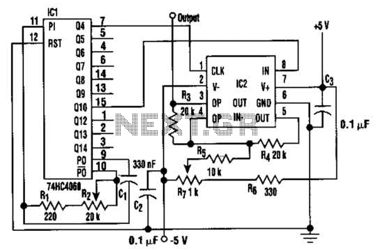
The circuit utilizes a high-order low-pass filter to effectively attenuate the higher frequency components of the square wave, which are primarily the harmonics. The -3 dB cutoff frequency is a critical parameter, determining the bandwidth of the filter and ensuring that the fundamental frequency is preserved while higher harmonics are significantly reduced. The MAX292 switched-capacitor filter is specifically chosen for its ability to achieve high precision and low distortion in signal processing applications.
The design of the circuit allows for a frequency response that remains stable over a wide range, from 0.1 Hz to 25 kHz. This capability makes it suitable for various applications that require precise sine wave generation, such as in audio signal processing, waveform generation for testing, and communication systems. The low distortion characteristic ensures that the output sine wave closely resembles an ideal waveform, which is essential for maintaining signal integrity in downstream applications.
Furthermore, the constant output amplitude throughout the frequency range is an important feature, as it ensures that the generated sine wave does not vary in amplitude with frequency changes. This stability is crucial in applications where consistent signal levels are necessary, such as in modulation schemes or when interfacing with other electronic components. Overall, this circuit design exemplifies an effective method for converting a square wave into a clean sine wave, suitable for a variety of electronic applications. In this circuit, a square wave is filtered by a high-order low-pass filter so that a -3-dB frequency will eliminate most harmonics of the waveform. As a result, the filter outputs a fundamental sine wave. This method is applied to generate a sine wave by using a switched- capacitor filter (MAX292) (see the figure).
This circuit offers wide frequency range (0.1 Hz to 25 kHz), low distortion, and constant output amplitude throughout the whole frequency range. 🔗 External reference
Related Circuits
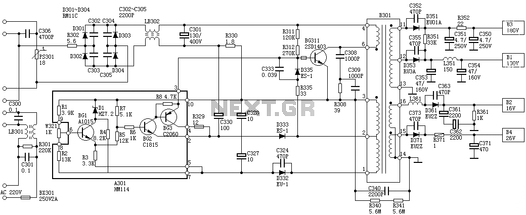
Oscillation: The positive terminal voltage of C310 is approximately 300V. The resistors R311 and R312 are connected to the switch BG311 at the B pole, while the B301 winding via the switching transformer (4) and (6) is connected to...
Using a K-12 tube amplifier with a NAD C542 CD player eliminates the necessity for a buffer or line-level preamplifier. The K-12 amplifier is characterized by its polite and sweet sound, embodying the warmth typical of its "hot bottle"...
XP power plug, FU fuse, ST temperature control, T1 low-voltage transformers, S1, S2 door interlock switch, S3 threshold control switch, RT thermal sensor, K1, K2 relay, EL furnace light, M1 wheel motor, M2 fan motor, T2 high-voltage transformer, C...
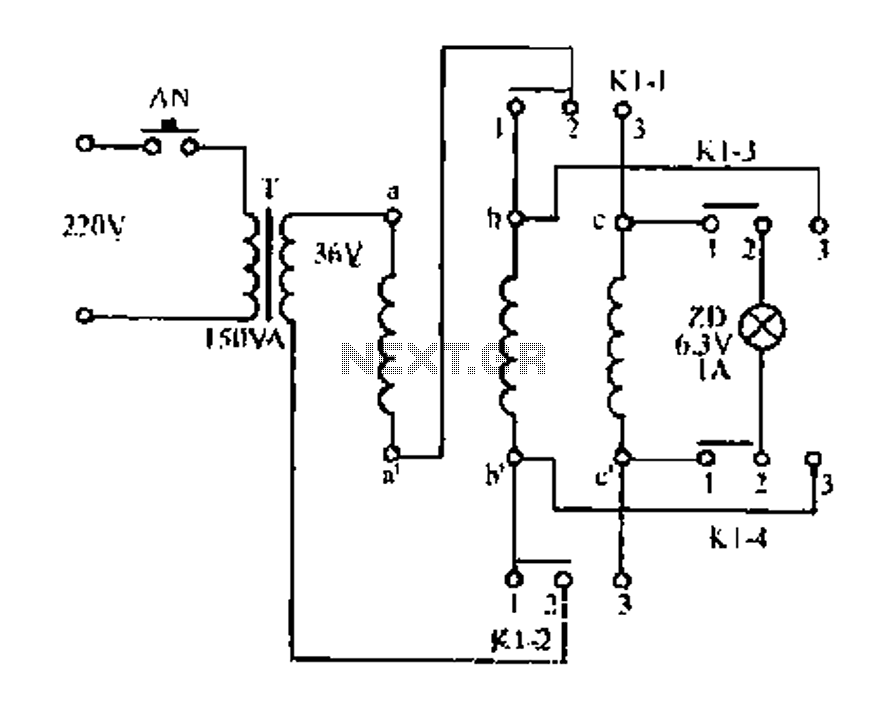
Figure aa, bb, and ce represent three-phase windings. A double throw switch Kl-1 to Kl-4 is positioned on the left side, connecting phases 1 and 2. At this point, aa and bb are in series with the secondary of...
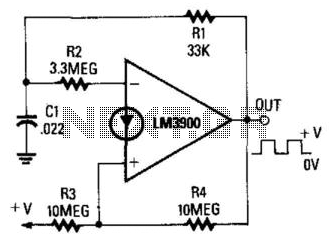
When the output is high, R3 and R4 are in parallel, and C1 charges through R1 until the current in R2 equals that at the non-inverting terminal. This action occurs when C1's voltage rises to 2/3 of the supply...
This is a basic 555 square wave oscillator designed to generate a 1 kHz tone for an 8-ohm speaker. In the circuit, the speaker is isolated from the oscillator by an NPN medium power transistor, which supplies more current...
Warning: include(partials/cookie-banner.php): Failed to open stream: Permission denied in /var/www/html/nextgr/view-circuit.php on line 713
Warning: include(): Failed opening 'partials/cookie-banner.php' for inclusion (include_path='.:/usr/share/php') in /var/www/html/nextgr/view-circuit.php on line 713