
transformer Low voltage oscillator for joule thief
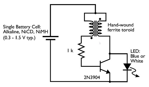
The described circuit involves a transformer that features two input leads for power supply and three output leads, which can be used for various applications, including lighting an LED. The blinking of the LED when connected to a dead AA battery indicates that the transformer may be functioning in a non-ideal manner, possibly due to the limited voltage and current supplied by the battery.
To explore the possibility of integrating a low voltage oscillator before the transformer, the use of a 555 timer IC is recommended. The 555 timer can be configured in astable mode to generate a square wave output, which can serve as the input signal to the transformer. This approach allows for the creation of a pulsed signal that can help energize the transformer more effectively than a static DC input.
In terms of schematic design, the following components would be necessary:
1. **555 Timer IC**: Configured in astable mode to produce a square wave output. The frequency can be adjusted using resistors and capacitors connected to the timer.
2. **MOSFET**: A suitable low voltage MOSFET can be used to switch the transformer, allowing the output from the 555 timer to control the power to the transformer.
3. **Transformer**: The transformer should be rated for low voltage operation, and its turns ratio will determine the output voltage based on the input voltage provided to the primary side.
4. **LED**: Connected to the output leads of the transformer, it will indicate when the transformer is energized.
The circuit should be powered by a suitable low voltage source, such as a 5V or 9V battery, depending on the specifications of the components used. The output frequency of the 555 timer can be tuned to optimize the performance of the transformer and the LED.
When designing the circuit, it is essential to ensure that all components are rated for the voltages and currents involved. Additionally, proper connections should be made to avoid short circuits, and adequate heat dissipation measures should be implemented for the MOSFET if it operates near its maximum ratings.
This setup provides a practical approach to utilizing a transformer at low voltages while employing an oscillator to enhance its performance.A transformer with 2 input leads and 3 output leads. I hooked up an LED to 2 of the output and put a dead AA battery on the input and the LED blinked for a second. I have no data on the transformer, but I am wondering if it is possible (and if so what is the schematic or instructions on how to do it) to put a low voltage oscillator before the transformer.
I know how to work with 12 volts with a power MOSFET and a 555 timer, but my question is if this is possible with low voltage. Any information is great. 🔗 External reference
Related Circuits
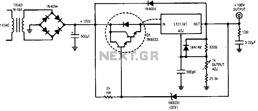
The regulator provides a 100 V output at 100 mA and can withstand shorts to ground. Even at a 100 V output, the LT317A operates in normal mode, maintaining a 1.2 V difference between its output and adjustment pin....
Below are a couple circuits you can use to produce a 32.768 KHz square wave from a common watch crystal. The output can be fed to a 15 stage binary counter to obtain a 1 second square wave. The...
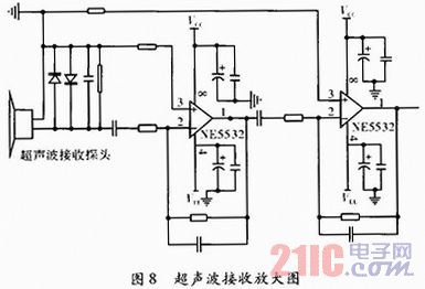
In industrial production, flow measurement is a widely used physical quantity measurement. Under specific circumstances, such as when vertical externally positioned installation probes are required for challenging pipelines like oil wells, it is necessary to design instruments and equipment...
This line-following robot sensor, or surface scanner for robots, is a compact, stamp-sized infrared proximity detector designed for short-range detection, operating within a range of 5 to 10 mm. The line-following robot sensor operates using infrared light to detect the...
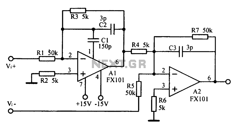
Common mode input voltage up to a difference of 100V enlarged circuit diagram. The circuit diagram described features a design capable of handling a common mode input voltage with a differential range of up to 100V. Such a configuration is...
The schematic illustrates the division of a crystal oscillator signal by the crystal frequency to achieve a precise 1-second time base with an accuracy of 0.01%. Two cascaded 12-stage counters (CD4040) create a 24-stage binary counter, with specific bits...