
Frequency Sine wave generator with MAX083

The sine wave output is fed into a TCA0372 1/2 opamp to achieve a gain from 1 to 5 (2V p-p, 10 V p-p), adjust the potentiometer and into a TCA0372 2/2 opamp buffer stage also present on the same IC.
Important: Adjusting the frequency needs a frequency counter, so this circuit should be used in conjunction with a frequency counter. The max current is 1A, but it is suggested not to exceed 0.5A to remain accurate. It requires a computer power supply with 12V, 5V, -5V, -12V, GND to operate; if a computer power supply is not available, a multivoltage mains transformer (15 watts is sufficient), diode bridges (low current 1-2 Amps), smoothing capacitors 10000uF 16V, and voltage regulators such as LM7905 and LM7912 should be used.
The circuit utilizes the MAX038 function generator, which is capable of producing various waveforms including sine, triangle, and square waves. The output frequency is adjustable and can be fine-tuned using the provided resistors and capacitors, allowing for a range of frequency outputs suitable for different applications. The TCA0372 power operational amplifier is employed to amplify the generated signal, providing a gain that can be adjusted according to the needs of the application.
For ESR measurement, the circuit operates at a frequency of 122 kHz, which is selected to minimize the effects of reactance in the capacitors under test. The circuit design incorporates a precision resistor to allow for accurate current measurement, facilitating the calculation of equivalent series resistance (ESR) based on the voltage drop across the capacitor.
The power supply requirements for this circuit involve multiple voltage levels, which can be achieved using a standard computer power supply or a suitable transformer and voltage regulation setup. The inclusion of smoothing capacitors and diode bridges ensures stable operation and minimizes ripple in the output signal.
Overall, this circuit is designed for precision measurements in capacitor testing applications, with careful consideration given to the selection of components and frequency characteristics to ensure accurate and reliable performance.This circuit uses the versatile MAX038 function generator. Although in this circuit some of the advanced characteristics of this IC are disabled, you can generate Sine, Triangle, Square waves (adjusting A0 and A1 pins see datasheet on www.maxim-ic.com if you want other waves, use a switch). The signal is amplified through a TCA0372 (from ONSEMI) Power opamp with current capability up to 1A and bandwitch up to 1 MHz.
I selected this particular frequency (122 Khz) because i needed a cheapo ESR-o-meter for my electrolytic capacitors to monitor their health as they have to discharge tens of amperes in less than 2 ms. At 122 KHz capacitive reactance is very low, and inductive reactance isn't so high, so forcing a current (es 200mA, using a precision resistor) through a capacitor and reading AC voltage drop accross it gives me an estimation of ESR (Vdrop/current).
Of course inductive and capacitive reactance are still present, but negligible. Operation: The 122 khz 2V p-p sine wave is generated by the MAX038 IC, its frequency can be calculated by the formula Freq (MHz) = Iin(uA) / C6 (pf) . Iin = 2,5V / R1 (25Kohm default). So the freq is 0,122 MHz . The resistor is for small adjustments, don't go under 10000 Kohm or above 40000 Kohm because the accuracy will drop.
If you want multifrequency just use the multiposition switch with 820 pF, 8,2 nF , 82nF , 820 nf for 122Khz range 12,2Khz range 1220 Hz and 122 Hz. Fine tuning can be done adjusting R2 , the frequency can vary from 1,7x (Vfadj = -2,4) to 0,3x (Vfadj = 2,4) of the main frequency (when fadj is at 0V).
The sine wave output is feed into a TCA0372 1/2 opamp to achieve a gain from 1 to 5 (2V p-p, 10 V p-p), adjust the potenziometer and into a TCA0372 2/2 opamp buffer stage also present on the same IC. Important: Adjusting the frequency needs a frequency counter, so this circuit should be used on conjunction with a freq couter.
The max current is 1A, but i would suggesto to not go above 0,5A to remain accurate. Needs a computer power supply with 12V,5V,-5V,-12V,GND to be operated, if you don't have one just use a multivoltage mains transformer (15 watt is enough) diode bridges (low current 1-2 Amps), smoothing capacitors 10000uF 16V, and voltage regulators such as LM7905 and LM7912. 🔗 External reference
Related Circuits
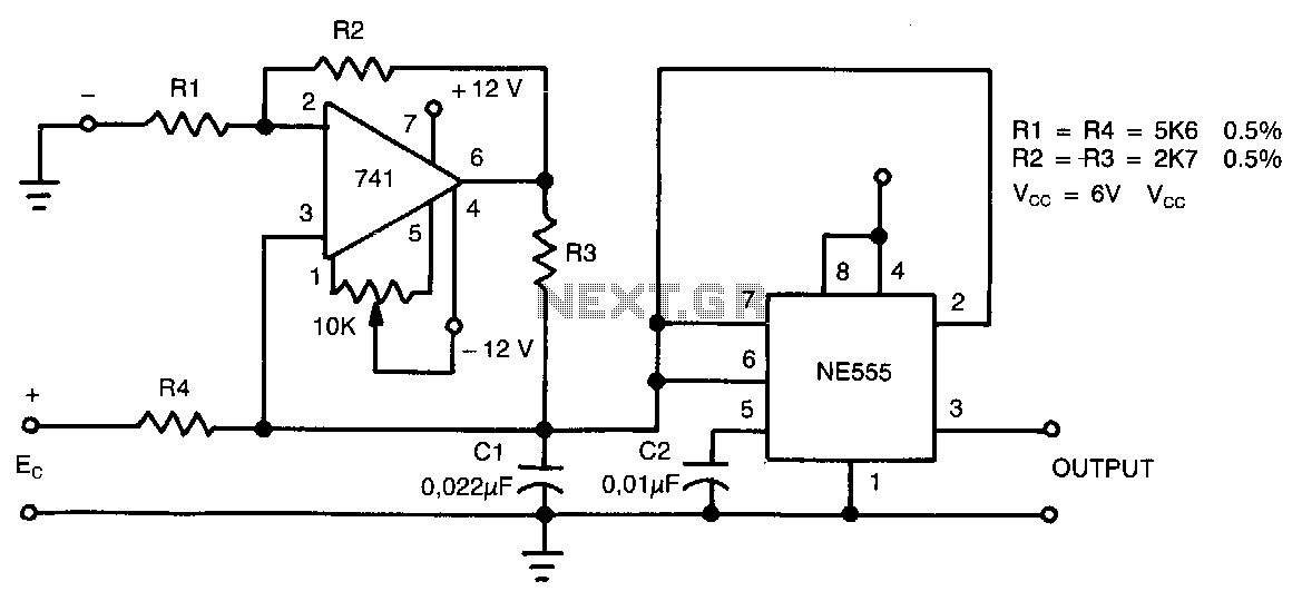
This circuit can accept positive, negative, or differential control voltages. The output frequency is zero when the control voltage is zero. The 741 operational amplifier forms a current source controlled by the voltage Ec to charge the timing capacitor...
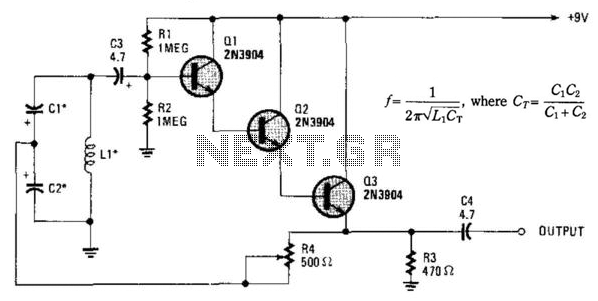
Essentially, this is a Hartley oscillator utilizing a triple-emitter follower, suitable for audio and low radio frequencies. The frequency is determined by the components, and at 1 kHz, a typical capacitor value would be 4.7 µF tantalum, although this...
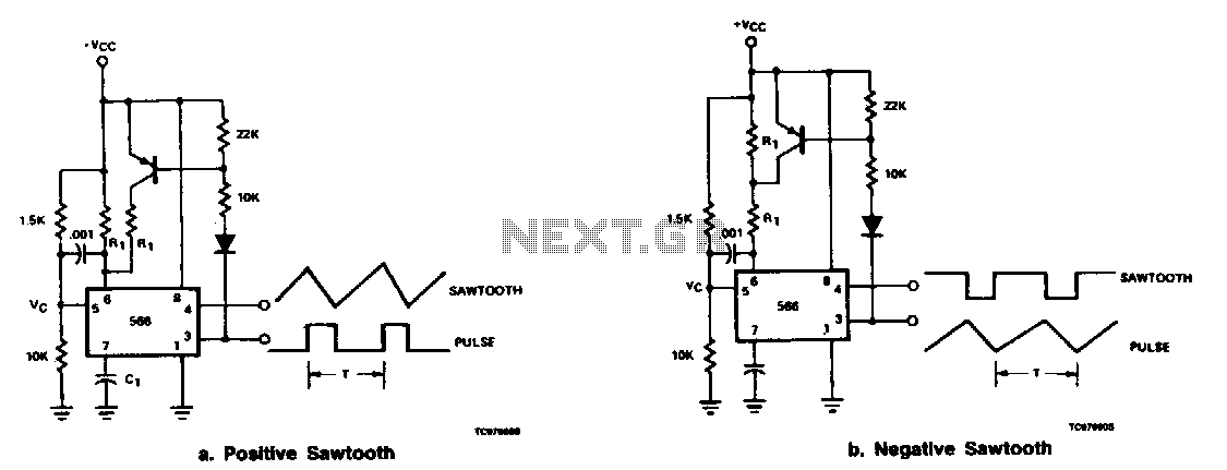
The output at pin 3 of the 566 can be utilized to deliver varying charge and discharge currents for capacitor Cl, resulting in a sawtooth waveform available at pin 4 and a pulse output at pin 3. It is...
Pulse Generator kit will generate a frequency in KHz which can form a good test gear project. This kit is based on the classic LM555 timer IC. Input - 12 VDC Max @ 40 mA. Range - jumper selectable...
This application note outlines the functionality of the MAX4929E, which manages the switching of all low-frequency signals (LoF) required for a 2:1 HDMI/DVI switch while providing high-level ESD protection for all external lines. It also details how the MAX4929E...
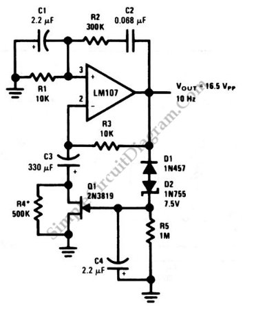
This is a Wien-bridge sine-wave oscillator circuit. This circuit utilizes negative-feedback stabilization to ensure that the gain does not exceed unity. The Wien-bridge oscillator is a type of electronic oscillator that generates sine waves. It consists of an amplifier and...