
Sine wave oscillator
The Wien bridge oscillator circuit is a classic configuration used to generate sine waves with high stability and low distortion. It typically consists of an operational amplifier (op-amp) and a combination of resistors and capacitors arranged in a bridge configuration. The circuit operates by balancing the impedances in the bridge to achieve oscillation at a specific frequency determined by the resistor and capacitor values.
In this particular implementation, the use of a Field Effect Transistor (FET) allows for dynamic adjustment of the resistance in response to the amplitude of the output signal. This feedback mechanism helps maintain a constant amplitude of oscillation, which is crucial for minimizing distortion. The FET acts as a variable resistor, enabling fine-tuning of the circuit's gain, which is essential for sustaining oscillation without leading to amplitude fluctuations that could result in signal distortion.
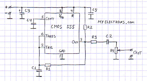
The frequency of oscillation is determined by the equation f = 1 / (2πRC), where R represents the resistance and C represents the capacitance in the circuit. By selecting appropriate values for R and C, the desired frequency can be achieved. Additionally, the full-wave rectification of the output signal is implemented to provide a stable DC voltage that is used to control the FET, ensuring that the oscillation remains consistent over time.
Overall, the Wien bridge sine wave oscillator is a sophisticated circuit that effectively balances the need for stable oscillation with minimal distortion, making it suitable for various applications in signal generation and waveform synthesis.The Wien bridge sine wave oscillator to introduce is the oscillator which works in the oscillation by returning(positive feedback) the oscillation output to the input. The point of this circuit is the negative feedback circuit to make the oscillation operation be stable.
The circuit to be using this time changes the resistance value of the Field E ffect-type Transistor(FET) at the d. c. voltage which rectified the oscillation output in the full wave and is making the oscillation operation be stable. The sine wave oscillator is the oscillator which is difficult to make because the distortion of the oscillation signal occurs compared with the square wave oscillator, the triangular wave oscillator.
🔗 External reference
Related Circuits
One of the simplest methods of metal detecting is through a beat frequency oscillator. The circuit consists of two balanced oscillators: one provides a reference signal, while the other acts as the detector element. The frequency of the reference...
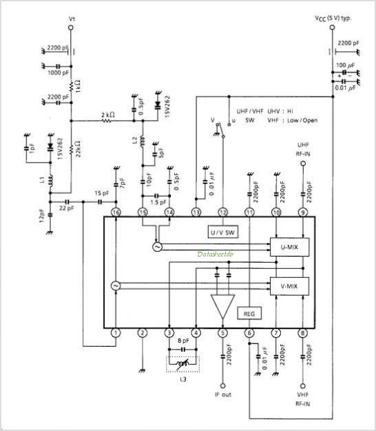
The receiver consists of multiple subassemblies, including an active antenna, an amplifier featuring regeneration control and band-switching circuitry, an AM detector, a power amplifier, and an output device such as an internal speaker, external speaker, or headphones. Additionally, it...
The form of a musical signal never resembles a square wave. The frequency range perceived by an average adult rarely exceeds 17 kHz. Therefore, the appropriateness of testing audio amplifiers with a 100 kHz square wave signal is often...
TA1317ANG is a deflection processor integrated circuit (IC) designed for large and wide picture tubes. It includes an electronic width (EW) correction circuit, a vertical distortion correction circuit, and a dynamic focus correction circuit. The device can control various...
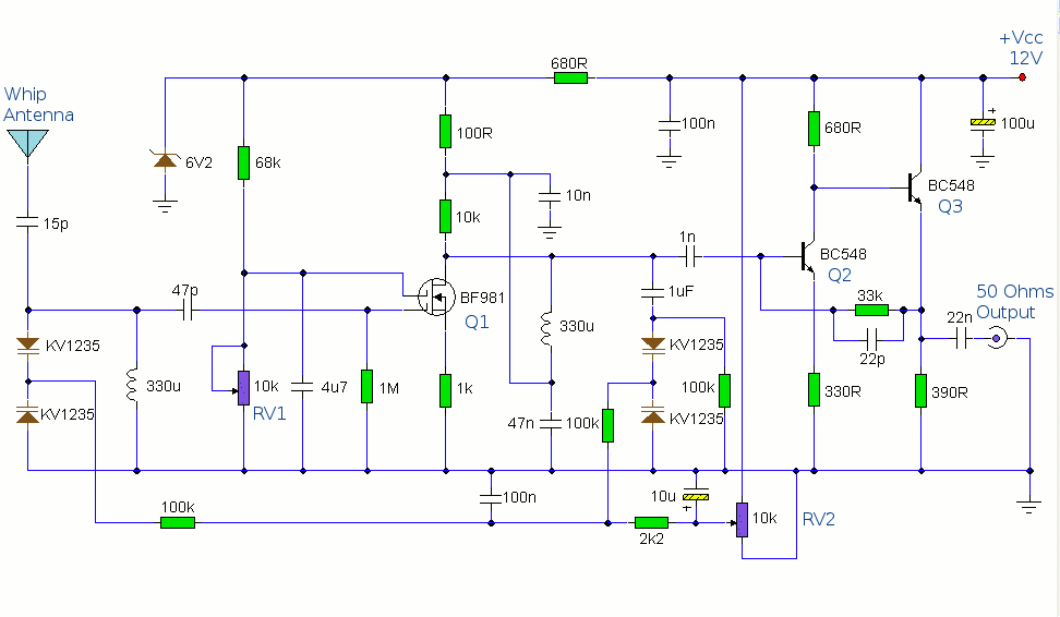
This circuit is designed to amplify the input from a telescopic whip antenna. The preamplifier is designed to cover the medium waveband from about 550KHz to 1650KHz. The tuning voltage is supplied via RV2, a 10k potentiometer connected to...
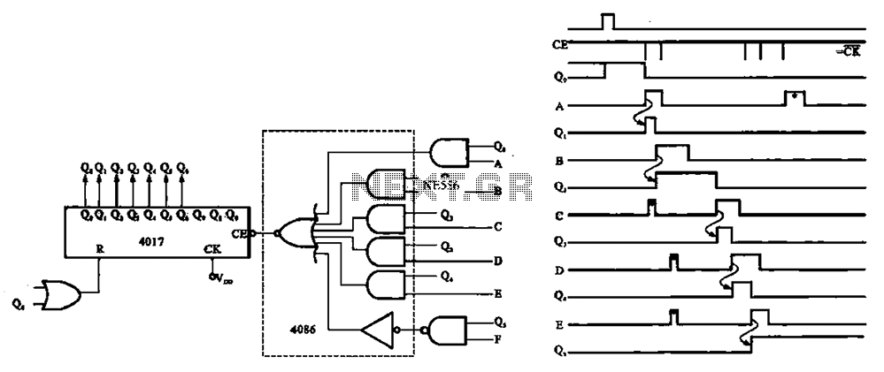
An asynchronous counter is illustrated in this circuit. It operates without a clock synchronization signal, making it suitable for use in a random counter or as an independent unit circuit. An asynchronous counter, also known as a ripple counter, is...
Warning: include(partials/cookie-banner.php): Failed to open stream: Permission denied in /var/www/html/nextgr/view-circuit.php on line 713
Warning: include(): Failed opening 'partials/cookie-banner.php' for inclusion (include_path='.:/usr/share/php') in /var/www/html/nextgr/view-circuit.php on line 713