
Asynchronous counter circuit and the signal waveform
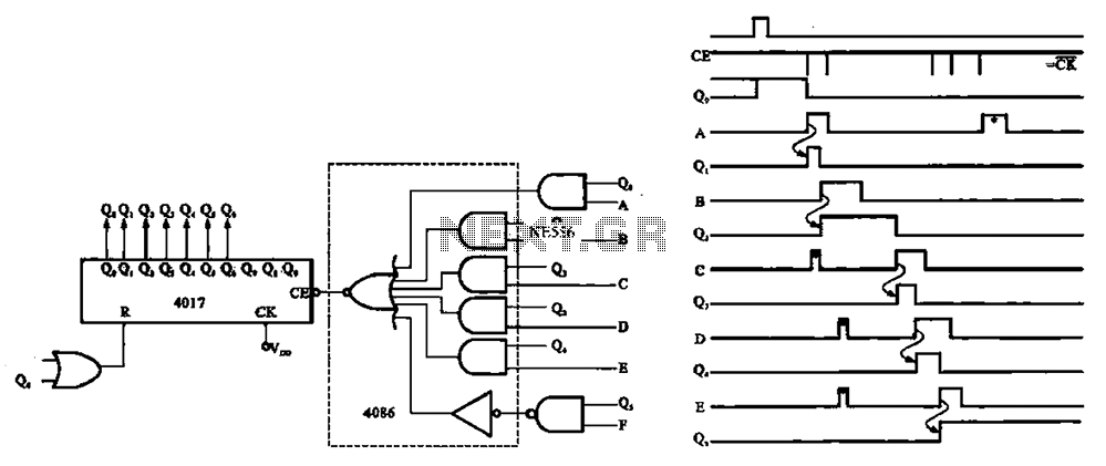
An asynchronous counter, also known as a ripple counter, is a digital circuit that counts in binary without relying on a common clock signal to trigger all flip-flops simultaneously. Instead, each flip-flop in the counter is triggered by the output of the preceding flip-flop, resulting in a ripple effect. This characteristic allows for the design of counters that can operate independently or in applications where precise timing is not critical.
The basic configuration of an asynchronous counter typically involves a series of flip-flops (commonly T or JK flip-flops) connected in a cascading manner. The first flip-flop is usually triggered by an external input signal, while each subsequent flip-flop is triggered by the output of the previous one. As a result, the output state of the counter changes in response to the input signal, with a delay introduced by the propagation time through each flip-flop.
The primary advantage of an asynchronous counter is its simplicity and ease of implementation, as it does not require a centralized clock signal. This feature makes it suitable for applications where the speed of operation is less critical, and cost-effective solutions are desired. However, the main drawback is that the propagation delay can lead to inaccuracies in counting at higher frequencies, as the ripple effect can cause the output to change in a non-uniform manner.
In practical applications, asynchronous counters are often used in digital clocks, frequency dividers, and event counters, where the counting does not need to be synchronized with a clock signal. The design of such counters can be tailored to meet specific requirements, such as counting in binary, BCD (Binary-Coded Decimal), or other number systems, depending on the configuration of the flip-flops and the logic circuitry employed. Asynchronous counter shown, this circuit no clock synchronization signal can be used in a random counter or independent unit circuit.
Related Circuits
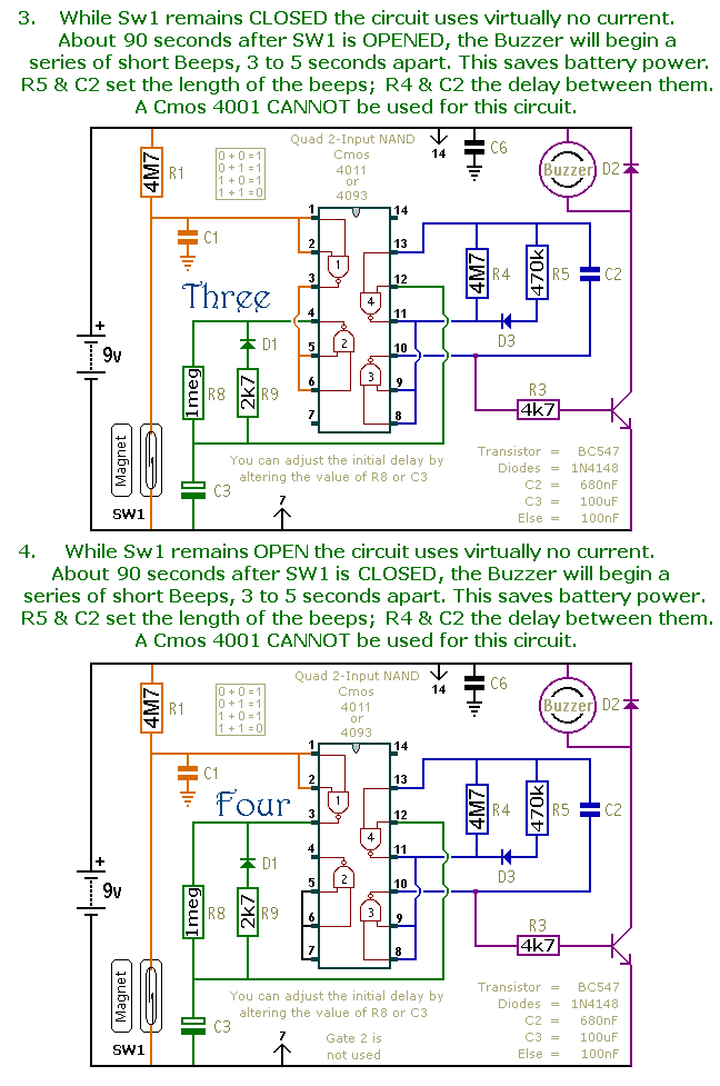
This is a collection of compact, self-sufficient alarm circuits designed for low standby current, making them ideal for battery operation. Some circuits are activated by normally-open and normally-closed switches, while others respond to variations in light or temperature. This...
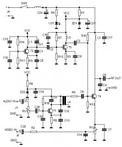
This is the circuit diagram of an audio/video modulator. The circuit converts audio and video signals into a UHF TV signal, allowing a video signal from a camera or other source to be connected to a standard TV set....

The individual expressed frustration while attempting to connect a circuit to a 15V supply, bypassing resistor R3 with a clip-on soldering heat sink. They noted that 555 timers emit a distinct odor when damaged. They have limited components remaining...
The Mark3 version of the Infrared extender is specifically designed to control appliances that utilize high-frequency modulated infrared remote signals. The Mark3 Infrared extender functions as a bridge between a standard infrared remote control and appliances that operate with high-frequency...
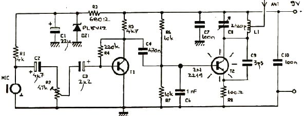
This FM transmitter electronic project operates in the FM band with a transmission power of approximately 250 mW. The circuit is straightforward and utilizes common transistors and electronic components. The T1 transistor, which may be a BC107, BC171, or...
The circuit features an adjustable prestage utilizing the AF279 transistor, while the natural oscillation mixer stage employs the AF280 transistor. The power circuit is mounted on a board with copper coating. The main coil specifications are as follows: L1,...