
Sine-wave shaper
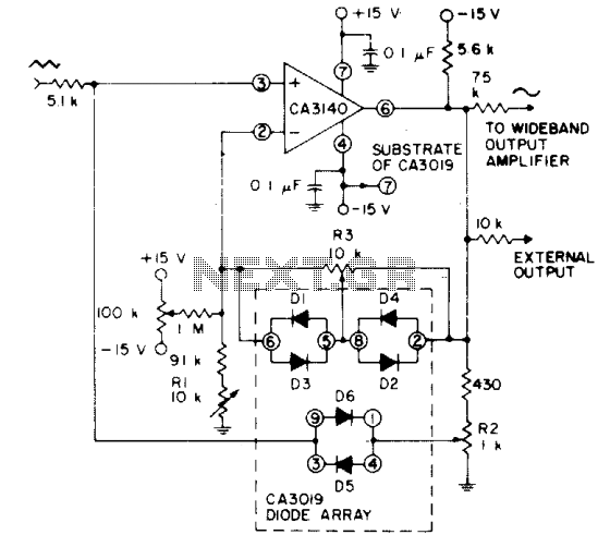
The circuit employs a CA3140 BiMOS operational amplifier, which is known for its high input impedance and low output impedance characteristics, making it ideal for voltage follower applications. The op amp is configured in a non-inverting configuration to ensure that the output voltage closely follows the input voltage, thereby providing a buffered output that maintains signal integrity.
The triangular waveform input, generated by a function generator, is fed into the non-inverting input of the CA3140. The output of the op amp is then connected to a diode array, specifically the CA3019. This array consists of multiple diodes configured to shape the waveform. The diodes allow for selective clipping and smoothing of the triangular waveform, effectively converting it into a sine wave.
The output from the diode array is then monitored, and adjustments can be made to the circuit components, such as the resistor values or diode selection, to optimize the output sine wave characteristics. The design aims for a total harmonic distortion (THD) of less than 2%, ensuring that the output signal maintains high fidelity and is suitable for applications requiring precision waveform generation.
Overall, this circuit exemplifies a practical approach to waveform shaping using operational amplifiers and diode arrays, demonstrating the versatility and effectiveness of analog components in signal processing applications.Uses a CA3140 BiMOS op amp as voltage follower, together with diodes from a CA3019 array, to convert a triangular signal (such as obtained from a function generator) to a sine-wave output with typical THD less than 2%. 🔗 External reference
Related Circuits

Utilize the Maxim MAX292 switched-capacitor filter integrated circuit to convert a square wave into a sine wave. The operational frequency range of the circuit spans from 5.2282 Hz to 8928.6 Hz when the microcontroller is functioning at a 16-MHz...
This circuit generates an accurate and adjustable sine-wave output by removing harmonics from a square wave. This circuit utilizes a harmonic filter to transform a square wave input into a sine wave output. The primary function of this circuit is...
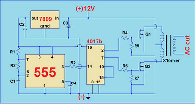
This project involves a simple 12V to 220V modified sine-wave inverter utilizing a 555 timer IC and a CD4017 decade counter. The inverter is capable of delivering 300W of continuous power and approximately 500W of maximum power output for...
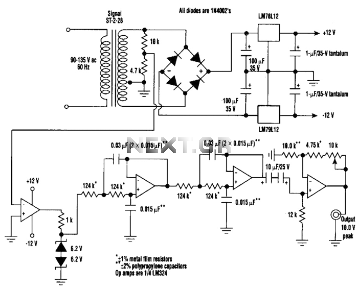
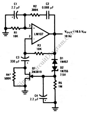
A highly stable 60-Hz sine wave can be delivered with this circuit, which offers a different and much simpler approach to achieving a stable amplitude. Capacitor coupling in the last stage removes any DC component caused by unequal Zener...
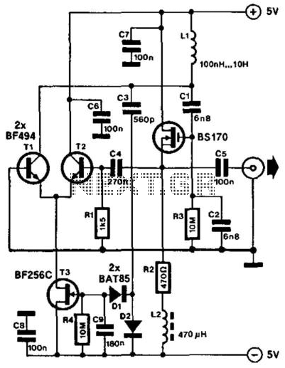
This compact LC oscillator operates within a frequency range of approximately 1 kHz to nearly 9 MHz and provides a low-distortion sine-wave output. The core of the circuit consists of a series-resonant circuit formed by inductor L1 and capacitors...
This is a Wien-bridge sine-wave oscillator circuit. This circuit utilizes negative-feedback stabilization to ensure that the gain does not exceed unity. The Wien-bridge oscillator is a type of electronic oscillator that generates sine waves. It consists of an amplifier and...