
Sine Wave To TTL Converter

This circuit typically employs a comparator to achieve the conversion from sinusoidal to TTL levels. The sinusoidal input signal is fed into the non-inverting input of the comparator. The inverting input is connected to a reference voltage, which can be set at half the supply voltage for optimal performance.
When the sinusoidal signal exceeds the reference voltage, the comparator outputs a high TTL signal (typically close to the supply voltage, such as 5V for standard TTL). Conversely, when the sinusoidal signal falls below the reference voltage, the output transitions to a low TTL signal (close to 0V).
To ensure proper operation, the circuit may include hysteresis, which helps to prevent false triggering due to noise or small fluctuations in the input signal. This is often implemented by adding a feedback resistor from the output of the comparator back to the non-inverting input, thereby creating a stable operating point.
The circuit can be powered by a dual supply or a single supply, depending on the design requirements. Additionally, the input signal should be AC-coupled through a capacitor to block any DC offset that could affect the performance of the comparator.
Overall, this circuit is suitable for applications where it is necessary to convert analog sinusoidal signals into digital TTL signals for further processing or interfacing with digital logic circuits.As the title implies, the present circuit is intended to convert sinusoidal input signals to TTL output signals. It can handle inputs of more than 100 mV.. 🔗 External reference
Related Circuits
This is a TMP01 Temperature-to-Frequency Converter circuit. Converting voltage to the frequency domain is another common method of transmitting analog signals. The TMP01 is a temperature sensor that outputs a frequency signal proportional to the temperature it measures. This circuit...
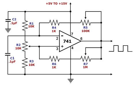
This is a square wave generator circuit. The primary component of this circuit is the 741, a general-purpose operational amplifier. The circuit operates with a single power supply voltage (Vs) that can vary between +5V and +15V. The square...
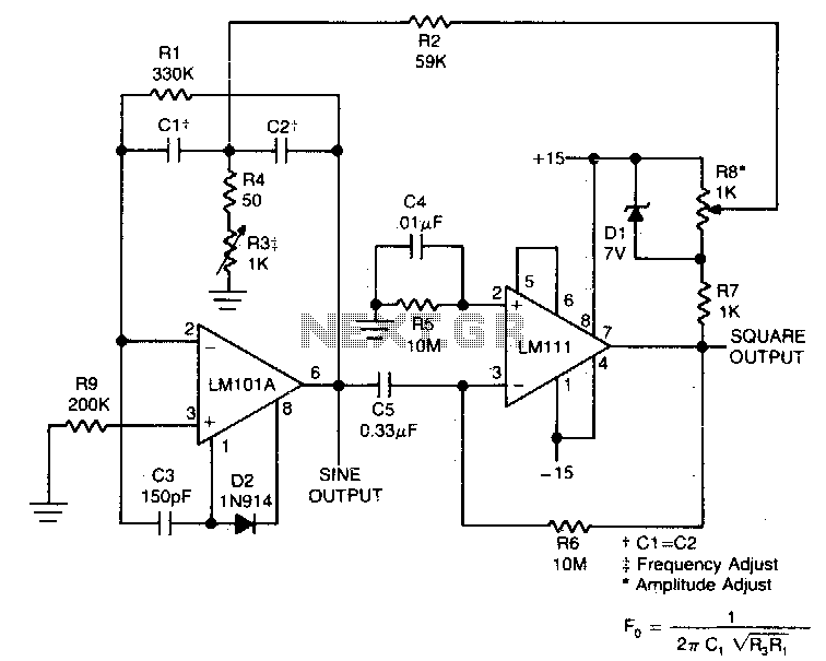
This circuit will provide both a sine and square wave output for frequencies ranging from below 20 Hz to above 20 kHz. The frequency of oscillation can be easily adjusted by changing a single resistor. This circuit is designed to...
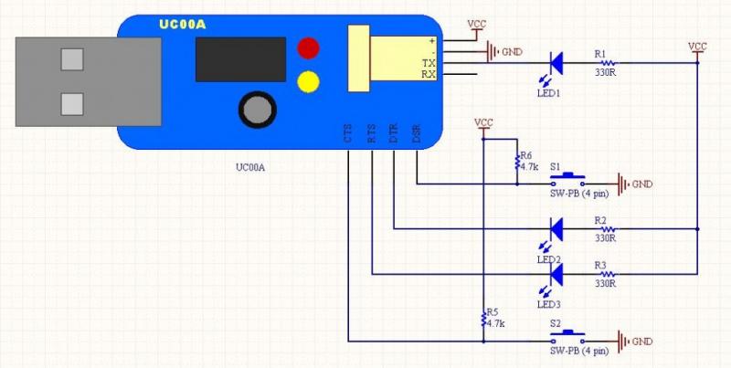
The LEDs operate in an active-low configuration (0), while the initial state of the switches is high (1). In other words, the PC software must send a low signal (0) to activate the LEDs, and if a low signal...
As depicted in the image, when the output current surpasses 40mA, the internal resistance of 50Ω in the XTR110 (R9) must be substituted with an external resistance, REXT. This external resistance is connected between pins 13 and 16. The...
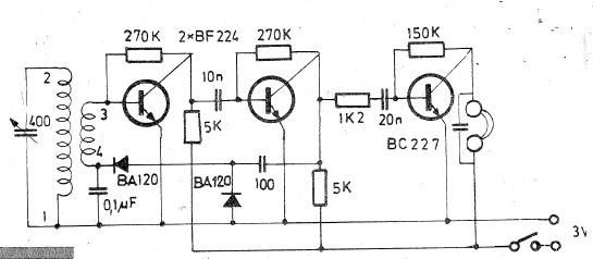
Oscillating circuits (coils) are constructed on a ferrite bar. For long wave reception, winding "1-2" consists of 135 turns, while winding "3-4" has 20 turns. For medium wave reception, winding "1-2" has 75 turns, and winding "3-4" has 7...