
Single Chip Memory Call Bell
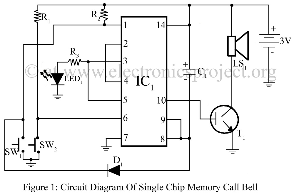
The single-chip memory call bell circuit is designed to provide a reliable notification system for visitors when the homeowner is not present. The core component of this system is the CD4011, which contains four independent 2-input NAND gates. The circuit leverages the NAND gates to create a memory function that retains the state of the doorbell even after the button is released, ensuring that the signal is captured and can trigger a notification.
When a guest presses the doorbell button, the circuit momentarily activates, sending a signal through the NAND gates. The arrangement of the gates is configured to form a flip-flop, which allows the circuit to maintain its state until it is reset. This memory function is crucial for ensuring that the signal is not lost immediately after the button is pressed.
In the schematic, the input from the doorbell button is connected to the first NAND gate. The output of this gate is fed into the second NAND gate, which is configured to create a feedback loop with the first gate. This feedback allows the circuit to maintain its output state even after the button is released. The output from the second NAND gate can be connected to an LED or a buzzer, providing a visual or audible indication of the guest's presence.
Additional components may include resistors and capacitors to stabilize the circuit and prevent false triggering. A power supply is also necessary to provide the required voltage to the NAND gates and any connected output devices.
Overall, this single-chip memory call bell circuit using the CD4011 NAND gate is an effective solution for doorbell applications, ensuring that homeowners are notified of visitors even in their absence.Single Chip Memory Call Bell using quad 2 input NAND gate CD4011 record when any guest come in absence of us.circuit diagram with description various doorbell project. 🔗 External reference
Related Circuits
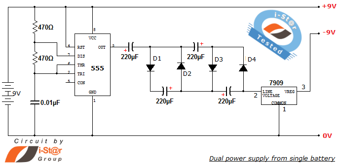
How to create a dual power supply unit using a single battery for laboratory purposes. Dual voltage power supplies are particularly needed for operational amplifier experiments and some instrumentation amplifiers. Additionally, certain low-power audio preamplifiers also require dual voltage...
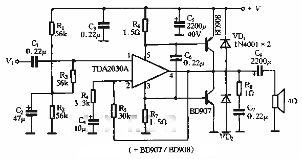
The rDA2030A TDA2030 is an enhanced version of the original product, with a maximum working voltage increased to 18V and a maximum output power of 18W. Additionally, harmonic distortion has been significantly reduced. The application circuit is illustrated. The rDA2030A...
The widespread application of Surface Mount Technology (SMT) in products such as computers, network communications, consumer electronics, and automotive electronics has led to increasingly complex, high-precision, and multifunctional electronic assemblies. Accurate testing techniques can enhance manufacturing efficiency and ensure...

This 6V battery-operated doorbell light circuit can be connected in parallel with any existing AC 230V doorbell. When the doorbell switch is pressed, the bell sounds as usual, and the AC mains supply available across the doorbell is routed...
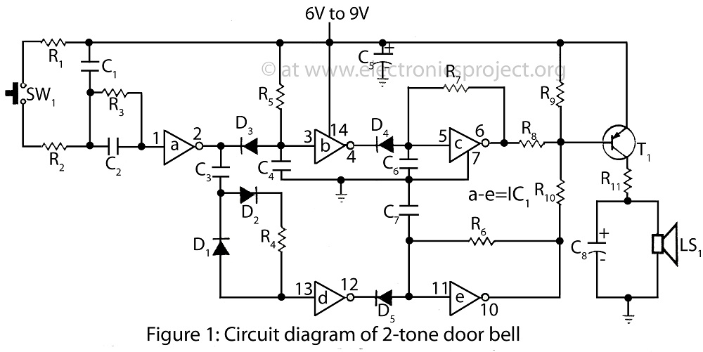
The project presented involves a verified circuit diagram for a two-tone doorbell that produces a "ding-dong" sound. It is part of a collection of various doorbell and alarm projects. The two-tone doorbell circuit typically utilizes a combination of capacitors, resistors,...
Is it possible to use DRAM with microcontroller AVR? Yes, it is possible. Jesperh has proved it. He hooked up a DRAM to a small processor (in this case an Microcontroller Atmel 8515), and handle the RAS/CAS sequencing and...