
Single chip pump controller
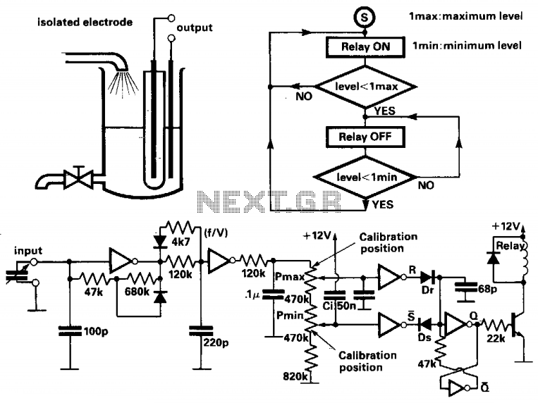
The maximum level (C1 max) can be set within the range of 65 pF to 120 pF, while the minimum level (C1 min) can be adjusted between 0 pF and 25 pF.
This circuit utilizes a bang-bang control mechanism, which is a type of on/off control system that provides rapid response to changes in the measured liquid level. The capacitive level meter detects the liquid level by measuring changes in capacitance caused by the presence of liquid in the tank. The first inverter, configured as a Schmitt oscillator, converts the capacitance measurement into a frequency signal. The frequency output is inversely proportional to the capacitance; thus, as the liquid level rises and capacitance increases, the output frequency decreases.
The second inverter operates as a monostable multivibrator, converting the frequency signal into a corresponding voltage level. This voltage level is then used to compare against preset thresholds for the maximum and minimum liquid levels, which are adjustable via potentiometers. The comparator circuits determine whether the liquid level is within the acceptable range and control the pump accordingly. If the level falls below the minimum threshold, the pump is activated to fill the tank, and if the level exceeds the maximum threshold, the pump is turned off.
The design allows for flexibility in setting the operational limits for the tank, ensuring that the liquid level is maintained within a specific range to prevent overflow or dry running of the pump. The use of capacitive sensing provides a non-contact method for level measurement, enhancing the reliability and longevity of the system.This circuit controls the level of a tank using a bang-bang controlled electrical pump. The actual level of liquid is measured by a capacitive level-meter. The first inverter performs as a capacitance to frequency converter. It is a Schmitt oscillator and its frequency output decreases as the capacitance increases. The second inverter is a monostable which performs as a frequency to voltage converter (f/V). Its output is applied to the maximum and minimum level comparator inputs. Maximum and minimum liquid levels may be set by the potentiometers. The maximum level (1 max) may be preset between the limits: 65 pF less than C (1 max) less than 120 pF. The minimum level is presetable and the limits are: 0 less than C (1 min) less than 25 pF. 🔗 External reference
Related Circuits
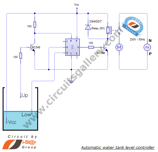
The automatic water level controller circuit is a straightforward engineering project that can automatically switch a domestic water pump on and off based on the water level in a tank. This motor driver circuit can be implemented at home...
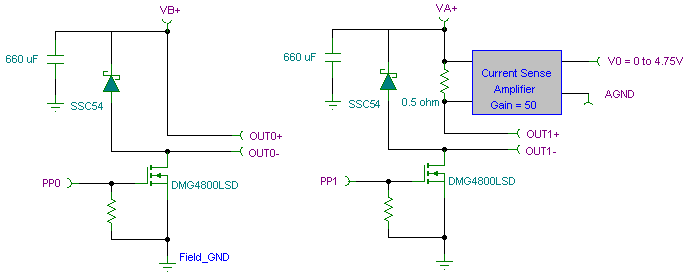
The PWM pulse width modulation controller board enables 9S12/HCS12 microcontrollers or PIC microcontrollers to output 8 channels, each capable of delivering 5 DC amps, while incorporating current sensing for the PWM waveform. This PWM driver circuit is suitable for...
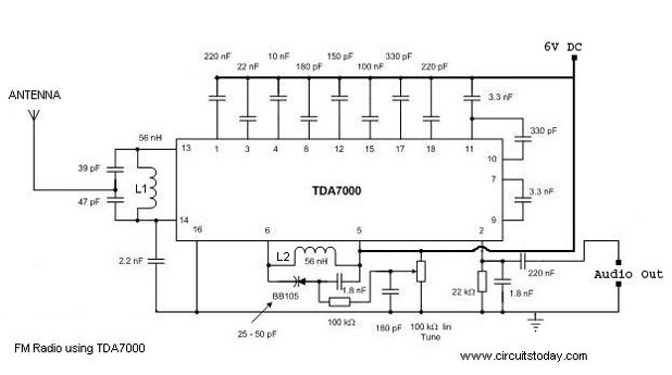
A simple FM radio circuit with a diagram and schematic using the IC TDA 7000. This low-cost single-chip FM radio circuit design is easy to assemble and is suitable for creating a portable FM radio. The FM radio circuit utilizing...
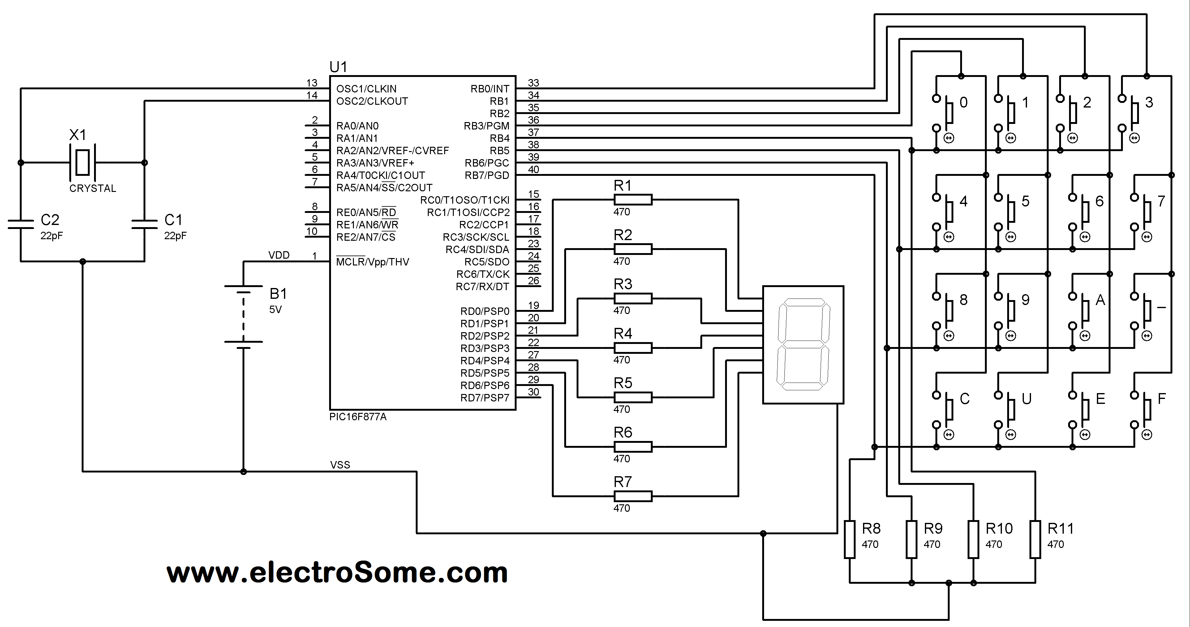
A matrix keypad is a highly useful and user-friendly component in the design of applications such as calculators and telephones. It consists of push-button switches arranged in rows and columns. For instance, interfacing a 4x4 (16 keys) matrix keypad...
The ZN414 integrated circuit (IC) contains a complete automatic gain controlled AM receiver within a compact three-pin package. With only a few external components, it is possible to construct a simple radio that offers excellent selection and reception capabilities....
This document presents a very low-power monolithic 1.9GHz silicon Low Noise Amplifier (LNA) that operates with a total current consumption of 1.75mA, which includes the bias circuit. The described Low Noise Amplifier (LNA) operates at a frequency of 1.9GHz, making...