
single chip am radio circuit
The ZN414 AM receiver IC is designed for optimal performance in compact applications, making it ideal for portable radio projects. The low operating voltage allows for the use of compact power sources, such as coin cell batteries, enhancing the feasibility of covert designs. The IC's wide frequency range enables reception of multiple AM signals, which can be fine-tuned using the external components in the tuning circuit.
The tuning circuit's components—L1 (inductor), C1, and C2 (capacitors)—play a crucial role in determining the frequencies that can be received. Adjustments to L1 can be made by varying the number of turns in the coil or by altering the spacing between the windings. This flexibility allows users to optimize the circuit for specific frequency bands, ensuring better reception quality.
The audio output capabilities of the ZN414 are limited to low-impedance devices, such as crystal earphones. For applications requiring higher audio output levels or compatibility with standard headphones, an LM386 audio amplifier can be integrated into the circuit. This addition enhances the audio performance and expands the range of output devices that can be utilized.
It is important to note that while the ZN414 is obsolete, its functional equivalents, such as the MK484 and ZN416, offer similar performance characteristics. However, sourcing these components may require some effort due to their specialized nature. Overall, the ZN414 and its counterparts provide a versatile solution for building AM radio receivers in compact formats, suitable for hobbyists and engineers alike.The ZN414 IC contains an entire automatic gain controlled AM receiver in a small three pin package. With only a few external components, a simple radio with excellent selection and reception can be constructed. Since the chip also uses a low supply voltage of only 1. 3V, 3V coin cell battery can make for a physically small circuit with many covert uses. The chip has a wide bandwidth of between 150KHz and 3MHz, so by playing with values in the tuning circuit you can pick up a wide variety of signals. The ZN414 is obsolete. The MK484 is it`s replacement, but like all special purpose ICs, it can be hard to find. At the time of this writing, there are many suppliers online that carry the IC. The ZN416 is functionally the same but with the additiion of a built in headphone amplifier. The audio output of the circuit is about 0. 1V peak to peak, which will drive a set of crystal earphones or other very high impedance phones. A small audio amplifier made with an LM386 will allow you to use modern dynamic headphones or a small speaker.
L1, C1 and C2 are the tuning circuit. By changing them around, you can change the range of frequencies the radio is capable of. Easiest to change is L1. Simply by altering the number of coils or moving the windings farther apart, you can shift the circuit to different frequency ranges. 🔗 External reference
Related Circuits
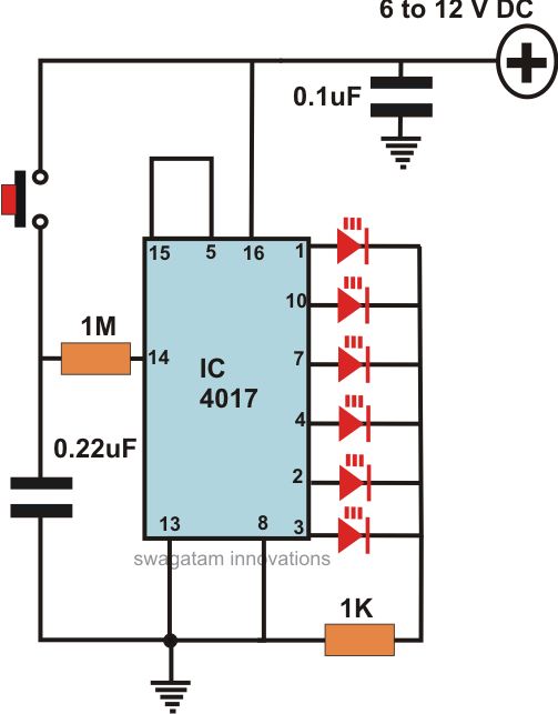
This article offers a circuit diagram and a discussion on CMOS logic and IC layout for creating a set of attention-getting LED running lights. It details a simple sequential LED flasher or light chaser that can be built, including...
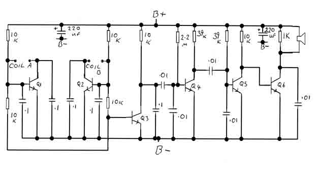
By adjusting the oscillators so their frequencies are very nearly the same, the difference between them is made audible as a beat note. This beat note changes slightly when the search loop is moved over or near to a...
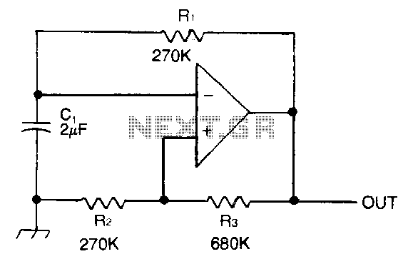
Capacitor C1 is charged through timing resistor R1 when the clock output is high. When C1 reaches the upper threshold voltage, the output signal decreases, and then C1 discharges through R1 until its voltage reaches the lower threshold point....
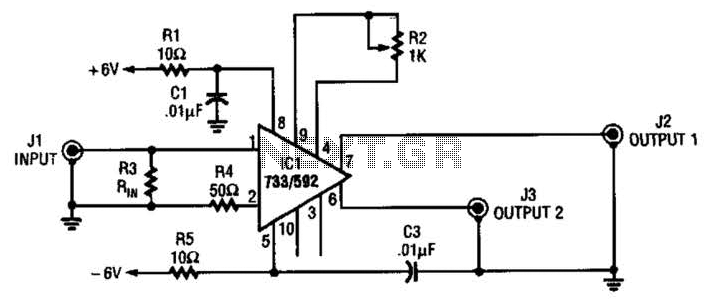
This circuit selects one of two channels using a logic signal. The unused channel is shorted out to minimize crosstalk. The bandwidth at -3 dB is approximately 8 MHz. It is recommended to buffer this circuit due to some...
This simple alarm circuit can effectively alert users to the presence of an intruder, providing notification before they even reach the doorstep. The circuit is designed to be straightforward and efficient, utilizing basic electronic components to create an effective security...
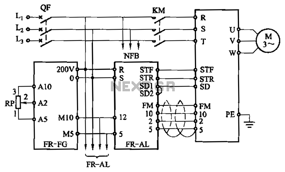
The main speed setting box FR-FG and the linkage setting operation box FR-AL (Mitsubishi inverter) enable synchronous operation of multiple motors. The circuit is illustrated. By utilizing these two external units, the speed of the primary motor (main motor...
Warning: include(partials/cookie-banner.php): Failed to open stream: Permission denied in /var/www/html/nextgr/view-circuit.php on line 713
Warning: include(): Failed opening 'partials/cookie-banner.php' for inclusion (include_path='.:/usr/share/php') in /var/www/html/nextgr/view-circuit.php on line 713