
Digital Sample And Hold
This circuit is a simple sample and hold configuration with offset adjustment capabilities. It operates on analog information within a specified timeframe, sampling segments of the input signal. Additionally, there is a variant utilizing the LM412 sample and hold circuit, which employs discrete components, including the MPF102 JFET transistor and LM412 dual operational amplifiers. In this version, the MPF102 prevents the source from charging the capacitor, while the LM412 is selected for its performance characteristics.
Another design features a low-drift sample and hold mechanism using two JFETs, Q1 and Q2, which provide the sample and hold capacitor, C1. During the sampling phase, Q1 creates a conductive path (Rds(on)) for C1, while Q2 manages the gate-source leakage current (IGSS).
Furthermore, a 555 timer can be integrated to minimize costs when adding a triggered sweep function to an economical oscilloscope. In this configuration, the timer is triggered by the input operational amplifier, which adjusts its flip-flop and disables its discharge transistor, facilitating the desired operation.
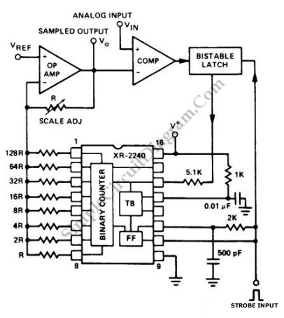
In summary, the discussed sample and hold circuits demonstrate versatility in capturing and maintaining analog signals for various applications, utilizing different components and configurations to achieve desired performance characteristics.If you need to hold an analog signal for infinite period then this digital sample and hold circuit is the solution. This circuit uses a Exar XR-2240 programmable timer/counter as main component. The Exar XR-2240 is triggered when strobe input is applied. The Exar XR-2240 start count when the timer is triggered and output of bistable latch is set t o high state. Staircase voltage is generate by this circuit at opamp output. This circuit need supply of 4-15V. Here is the schematic diagram of the circuit: If the level of analog input that will be be sampled is reached by the stair-case voltage, the Exar XR-2240 stop count because comparator changes state and bistable latch is activated. Then Opamp output voltage level corresponds to sampled analog input. Until next strobe signal, the sample is held by this circuit. This circuit has Minimum recycle time of 6ms. Sample and hold circuit is used to pick a signal and hold the level at its output, making it useful for analog digital conversion or other application where the processing need a constant level signal for the input.
The circuit Continue reading †’. This is a simple sample and hold with offset adjustment circuit. Sample and hold circuit is used to operate on analog information in a time frame which is expedient. This circuit works by sampling a segment of the information and Continue reading †’. This is a LM412 sample and hold circuit. This circuit uses discrete components. This circuit also uses MPF102 JFET transistor and LM412 dual op-amps. The source is prevented to charge the capacitor by the MPF102. The LM412 is used because Continue reading †’. This is a circuit of low drift sample and hold. This circuit uses two JFET, Q1 and Q2 that provides the sample and hold capacitor, C1. Q1 provides a path, Rds(on), for C1 and turned on during sample. Q2 IGSS Continue reading †’. We can use the 555 timer to hold the cost down of adding a triggered sweep to an economy oscilloscope. The timer is triggered by the circuit`s input op amp, adjusting its flip-flop and cutting off its discharge transistor so Continue reading †’.
🔗 External reference
Related Circuits
The WPG DM8168 DaVinci high-definition video System on Chip (SoC) offers multiple DVR/NVR surveillance solutions, utilizing the MT9M033 image sensor as a key component in safety monitoring systems. This solution is complemented by Conexant's line of multi-channel video surveillance...

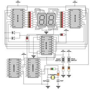
This circuit provides a visual 9-second delay using a 7-segment digital readout LED. When the switch is closed, the CD4010 up/down counter is preset to 9, and the 555 timer is disabled with the output held high. The circuit utilizes...
The 555 timer is utilized as a clock source to drive the RS7490 decimal counter, providing a BCD output to a 7-segment LED display. The clock frequency can be adjusted by changing the value of resistor R1. The circuit operates...
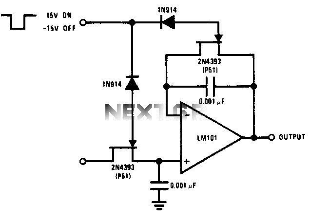
The logic voltage is applied simultaneously to the sample and hold JFETs. By matching input impedance and feedback resistance and capacitance, errors due to the drain-source on-resistance (rdson) of the JFETs are minimized. The circuit employs a sample and hold...
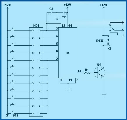
Circuit diagram schematics of electronic keys, electronic locks, digital electronic locks, transistor code locks, and combination electronic locks. The circuit schematics for electronic locking mechanisms encompass a variety of designs tailored to enhance security and convenience in access control systems....
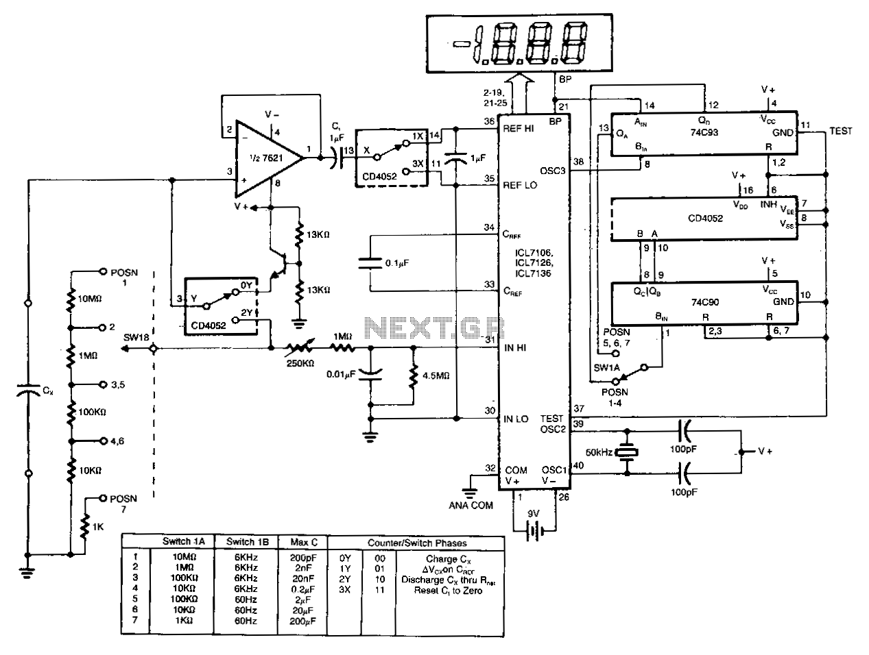
The circuit charges and discharges a capacitor at a crystal-controlled rate and stores the change in voltage achieved on a sample-and-difference amplifier. The current flowing during the discharge cycle is averaged and ratiometrically measured in the analog-to-digital converter (ADC)...
Warning: include(partials/cookie-banner.php): Failed to open stream: Permission denied in /var/www/html/nextgr/view-circuit.php on line 713
Warning: include(): Failed opening 'partials/cookie-banner.php' for inclusion (include_path='.:/usr/share/php') in /var/www/html/nextgr/view-circuit.php on line 713