
single phase half wave thyristor
In the Single Phase Half-Wave Rectifier circuit employing a thyristor, the operation is fundamentally different from traditional diode-based rectifiers. The SCR allows for controlled rectification, which is advantageous in various applications, such as motor control and power regulation. The firing angle (α) is a critical parameter, as it determines the point in the AC cycle at which the SCR begins to conduct. This angle is adjustable via the potentiometer, enabling fine-tuning of the output voltage and current characteristics.
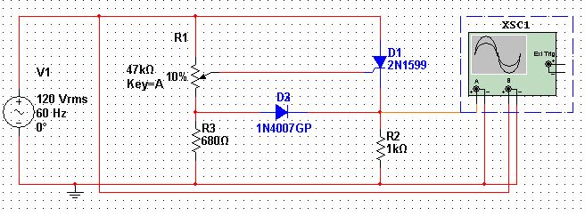
The circuit typically consists of an AC power source, a thyristor, a load resistor, and a firing circuit. The firing circuit may include a resistor-capacitor (RC) timing network or other triggering mechanisms to create the required delay angle. When the AC voltage rises and reaches the threshold defined by the firing angle, the gate terminal of the SCR receives a triggering pulse, turning the thyristor on and allowing current to flow through the load.
During the positive half cycle of the AC input, as the SCR is triggered, the voltage across the load resistor increases, following the input waveform but only after the specified delay. This results in a clipped output waveform, where the initial portion of the half cycle is absent from the load. In the negative half cycle, the SCR remains off, preventing current flow and resulting in zero voltage across the load resistor during this phase.
The graphical representation of the output voltage clearly illustrates the relationship between the firing angle and the load voltage. The area under the curve during conduction represents the power delivered to the load, which can be adjusted by varying the firing angle. This characteristic makes the thyristor-based half-wave rectifier an effective solution for applications requiring variable control of power delivery.
Overall, the Single Phase Half-Wave Rectifier using a thyristor exemplifies the principles of controlled rectification in power electronics, showcasing the importance of firing angle control in managing output characteristics.In some of my previous posts, we have seen the simulations of half wave and full wave rectifiers using simple diodes. Now in this post, I would like to move on to power electronics domain with the first post being Single Phase half wave rectifier using thyristor .
In a thyristor or a so called SCR (Silicon controlled rectifier) circuit, the thyr istor is turned on after a delay angle alpha ( ±) using a firing circuit. ± is also called firing angle. So, in the circuit shown below, the SCR starts conducting only after a delay angle of ±, which is controlled by the potentiometer across the Anode and Gate terminals of the SCR. When the SCR starts conduction, the voltage appears across the load resistor of 1k © as shown in graph-2, otherwise during off condition of SCR, the voltage appears only across the SCR as shown in graph-3.
You can see the in the above graph that the voltage appears across the load only after a certain delay angle (firing angle). Conduction occurs only in positive half cycles, since during negative half cycles, the SCR is switched off.
Part of the sinusoidal waveform which do not appear across the load resistor appears across the thyristor as shown in the graph-3. These waveforms appear when the thyristor is on OFF mode 🔗 External reference
Related Circuits
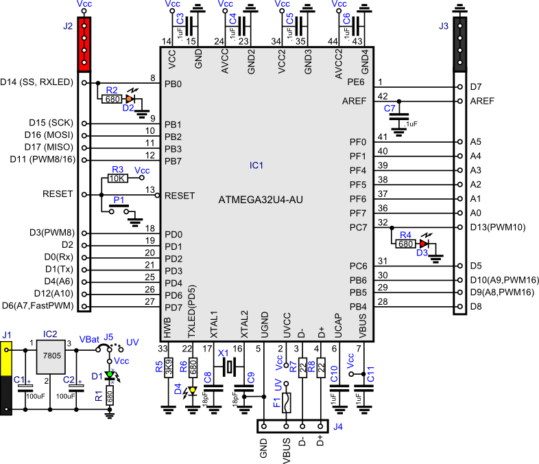
This project involves creating a clone of the Arduino Leonardo in a simplified manner. Consequently, the pin distribution does not conform to the standard Arduino layout. The Arduino Leonardo clone project focuses on replicating the functionality of the original Leonardo...
The JBL "Bass Wave" amplifier is a compact 100-watt amplifier featuring a built-in active filter that includes a single-pole high-pass filter at 10 Hz and a single-pole low-pass filter at 85 Hz. Priced at an affordable $50 USD, it...

This is another example of a closed-loop speed control system. It utilizes a single voltage supply and an L298 integrated H-bridge power amplifier capable of handling 24V. Similar to the previous example, it is also suitable for two-way speed...
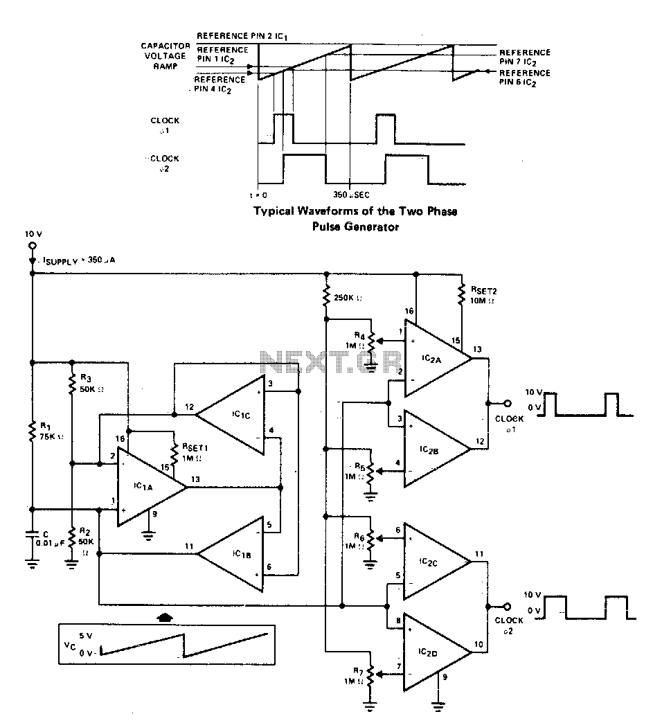
A two-phase clock generator utilizes two L161 integrated circuits to produce pulses with adjustable widths and phase relationships. Additionally, a ramp generator supplies input to two variable window comparators, which are configured using IC2A-IC2B and IC2C-IC2D, respectively. The two-phase clock...
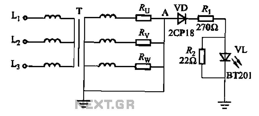
It is well understood that if the power transformer neutral line is disrupted, an unbalanced three-phase load can easily result in overvoltage conditions, potentially damaging electrical equipment such as household appliances and lamps. The neutral circuit alarm system is...
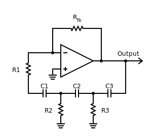
Phase-shift oscillator. An oscillator in which a network has a phase shift of 180 degrees. A phase-shift oscillator is a type of electronic oscillator that generates a sinusoidal output signal. It typically consists of an amplifier and a phase-shifting network...
Warning: include(partials/cookie-banner.php): Failed to open stream: Permission denied in /var/www/html/nextgr/view-circuit.php on line 713
Warning: include(): Failed opening 'partials/cookie-banner.php' for inclusion (include_path='.:/usr/share/php') in /var/www/html/nextgr/view-circuit.php on line 713