
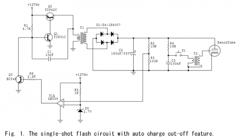
Single-Shot Auto-Charge Flash Circuit
It was also noted that discharging the capacitor with a higher voltage rating (400V version) resulted in an intense light explosion that damaged the interior of the Xenon tube. A potential issue with the circuit arises from Q2, which shorts the supply during normal operation, causing slight variations in the reference voltage over time. It is proposed that a 555-based oscillator could rectify this problem.
During tests, the capacitor was charged to 300V using a 12V DC supply. When the supply voltage decreased to 7V DC, the capacitor charged to 270V. Below 7V DC, the circuit becomes ineffective as the Xenon tube will not ignite. Therefore, the operational range for the DC supply is between 7V and 12V.
The circuit incorporates a voltage divider with R2 and R3 to scale the voltage across C2, ensuring safe monitoring and control of the charging process. The LM358 comparator plays a crucial role in regulating the charge by providing feedback on the capacitor's voltage level. The zener diode stabilizes the reference voltage, which is essential for the proper functioning of the comparator.
Transistor Q3 acts as a switch to control the oscillator's operation. When the capacitor reaches the desired voltage, Q3 activates, effectively turning off the oscillator and preventing further charging, which is critical for maintaining the safety and integrity of the circuit.
The observed behavior during discharging with a higher voltage rating highlights the importance of component ratings and the potential for damage if the circuit is not designed to handle such conditions. The suggestion to implement a 555-based oscillator indicates an understanding of circuit stability and the need for a reliable reference voltage to ensure consistent operation.
In summary, the circuit is designed for efficient voltage regulation and capacitor charging, with careful consideration given to component ratings and operational limits. The proposed modifications aim to improve the circuit's reliability and performance during various operational scenarios.There is a voltage divider composed of R2 (10M) and R3 (100K) which effectively divides the voltage across C2 by about 100. Also note the ground of C2. It is connected to the inverter ground for reference. I used an LM358 comparator to keep track of the charging status. A 2.7V zener diode makes the reference voltage at about 2.85V (it’s slightly overdriven by 1K resistor).
The voltage across R3 will be about 2.85V when the cap is charged to 285V. Till that time,
the comparator output is low, and hence Q3 is OFF. After that, Q3 will be turned on and saturated. And it will steal the base current from Q1 and fix the VBE of Q1 to about 0.2V. That act will turn off the oscillator and stop the charging process. During the experiments, with the values shown in Fig. 1, the capacitor was charged to 300V in about 4 sec. and was kept at that value till I pressed the fire button.
I also observed that discharging the cap with a higher voltage rating, i.e. 400V version, will make an intense light explosion such that the interior of the Xenon tube will be damaged, as shown in Fig.
3. There is one problem with the circuit. During normal operation, Q2 shorts out the supply and the reference voltage changes slightly over the time. I believe that a 555 based oscillator will solve this problem.
During the tests, the cap was charged to 300V with 12VDC.
When the supply voltage lowered to 7VDC, the cap was charged to 270V. Below 7VDC is not useful since the Xenon tube will not fire. So the useful range for the DC supply is 7-12V for this circuit. By 4beowulf7 - [email protected]
Related Circuits
The circuit on this page is for a simple light detector circuit board that has 8 detectors that can be used with visible or infrared light systems. The detectors use LM339 voltage comparators as the active element. Phototransistors or...
An audio test oscillator circuit typically produces a square wave if the oscillation frequency is low enough in relation to the amplifier's bandwidth. This circuit features a crystal-controlled oscillator designed for low-frequency sine wave generation, characterized by low distortion,...
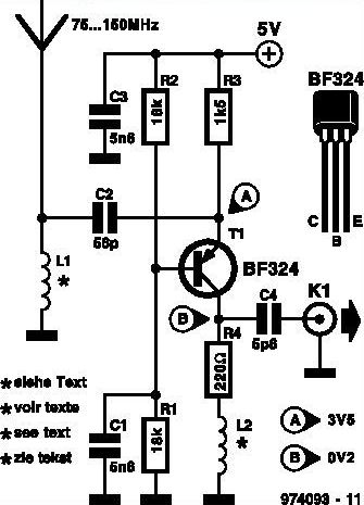
This inexpensive FM radio receiver antenna booster utilizes the BF324 TO92 style PNP transistor in a grounded-base configuration. The circuit can be employed as a... The FM radio receiver antenna booster circuit is designed to enhance the reception capabilities of...
This circuit is designed for the selection of alternative sources. It integrates mechanical selection through a rotating switch S1, electronic control of relays RL1 to RL10, and optical indication of the selection via the display DSP1. The circuit operates by...
This article discusses the Gadgets, Gizmos, and Arduino (ATMega328). The content is straightforward and informative. The components mentioned in this article can enhance the understanding of the subject. For instance, readers can find and purchase components such as the...
The standard Class AB audio power amplifier allows for direct coupling of the amplifier's output to speakers. This is beneficial as it eliminates capacitors or transformers that could compromise sound quality. The speakers are connected directly to the amplifying...
Warning: include(partials/cookie-banner.php): Failed to open stream: Permission denied in /var/www/html/nextgr/view-circuit.php on line 713
Warning: include(): Failed opening 'partials/cookie-banner.php' for inclusion (include_path='.:/usr/share/php') in /var/www/html/nextgr/view-circuit.php on line 713