
Proximity Alarm I Circuit

IC1 functions as a critical component in a security system or alarm device, leveraging the interaction between its oscillators and amplifier to create a responsive alert mechanism. The low-frequency audio signal oscillator serves as the primary sound generator, producing a tone that is amplified for audible output through a speaker. This audio output is essential for alerting users to a potential security breach or other significant events.
The high-frequency oscillator's design is deliberately unstable, which allows it to remain inactive until it detects changes in the RC network. The combination of R2 and PL forms a variable resistor, where decreasing the resistance of PL enhances the oscillator's sensitivity. This sensitivity is crucial for detecting even minor changes in capacitance, which can occur when a person approaches the antenna loop. The capacitance introduced by the loop, along with the inherent capacitance of the human body, effectively activates the high-frequency oscillator.
Once activated, the high-frequency oscillator triggers the low-frequency oscillator, resulting in the generation of an audio tone. The latching feature of the IC ensures that once the alarm is triggered, it remains active until the power supply is interrupted. This design prevents accidental deactivation and ensures that alerts are reliably communicated. Overall, the integration of oscillators and amplifiers in IC1 creates a robust mechanism for detecting and signaling events, making it an effective element in various electronic applications. IC1 contains several oscillators and an amplifier. The low-frequency audio-signal oscillator is used to supply an input to the amplifier. That signal is the audio tone that is amplified, then supplied to the speaker by the amplifier. The high-frequency oscillator is purposely set to be very unstable. It is dormant or off` until the resistor-capacitor (RC) network is changed. The resistance (R) in this case is made up of R2 and PL As the resistance of PI is decreased, the unit becomes more sensitive (more unstable), and less capacitance (C) is needed to cause the oscillator to oscillate. The capacitance required is provided by C2 and by any capacitance introduced via the antenna loop. When you come near that loop, your inherent body capacitance causes the high-frequency oscillator to begin to oscillate, which then causes the low-frequency oscillator to be switched on internally. Once the alarm is sounding, the IC is designed so that it latches, that is, it stays on until the power to it is switched off.
🔗 External reference
Related Circuits
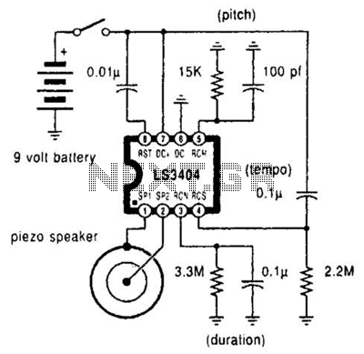
A high-quality melody circuit produces a slow decay waveform that generates chime-like notes. The pitch, tempo, and duration of the notes are all adjustable. The melody circuit is designed to offer a versatile sound generation capability, making it suitable for various...
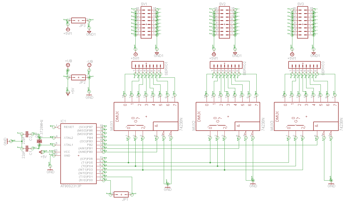
A serial servo controller is being developed to enhance knowledge of electronics and assembly language as part of a hexapod robot project. Initially, the ATTiny2313 microcontroller was utilized; however, it became evident that additional I/O channels were necessary. Consequently,...
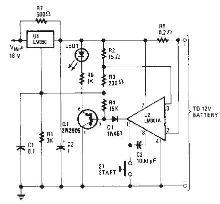
The LM350 car battery charger circuit is a high-performance device designed to efficiently charge gelled lead-acid batteries and automatically terminate the charging process once the battery reaches full charge. This circuit provides a charging current of 2A when the...
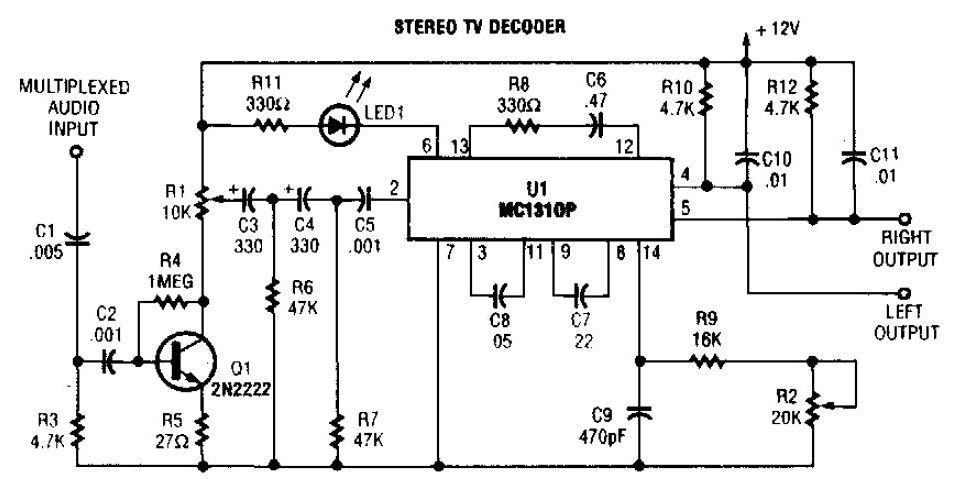
A simple stereo TV decoder circuit built with the MC1310P. Transistor Q1 functions as an audio amplifier, while U1 operates at a 31.5 kHz subcarrier frequency, which is similar to a 38 kHz FM multiplex. The pilot frequency is...
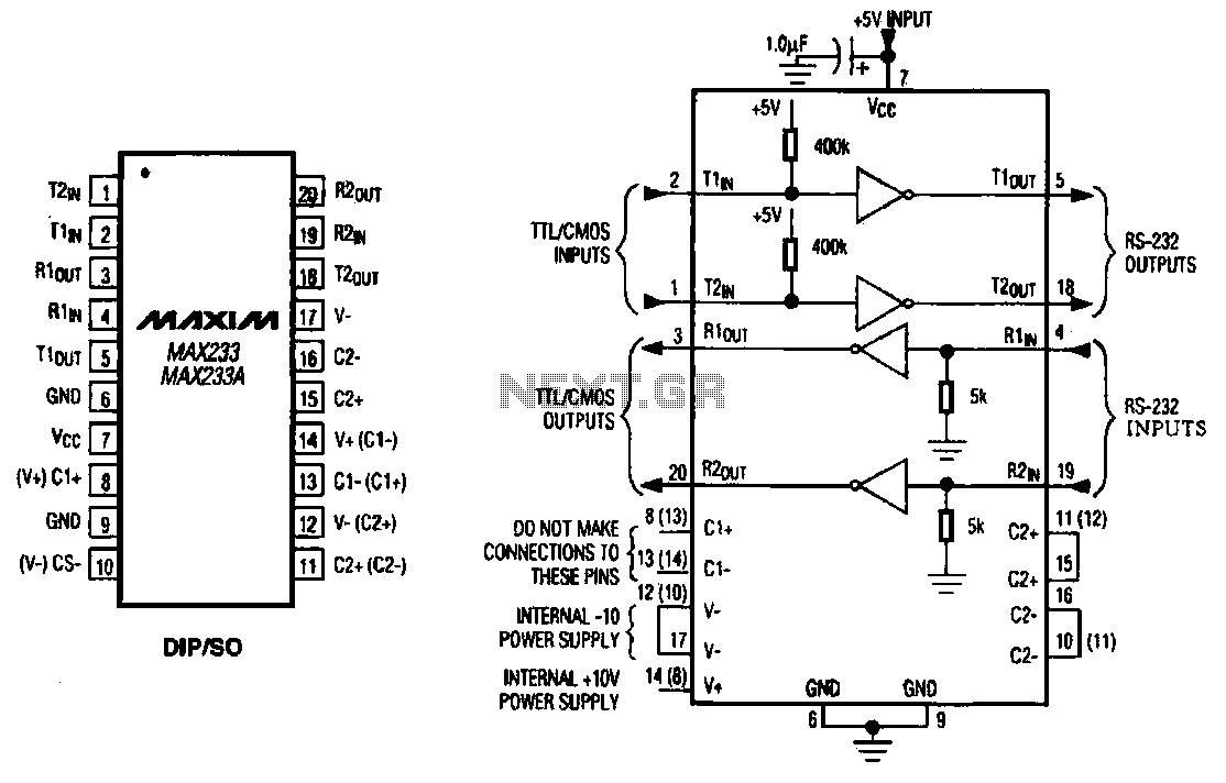
The MAX233 / 233A is a multi-channel data interface circuit featuring dual output and dual input driver circuits. It is designed for small digital products and multimedia equipment to facilitate data transmission. The MAX233 / 233A integrates multiple functions to...
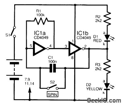
This circuit is designed to electronically simulate the tossing of a coin using a 4049 hex inverter integrated circuit (IC). It employs two of these ICs, specifically IC1a and IC1b, which are configured as an astable oscillator. This configuration...