
Sinusoidal 3Hz To 300Khz Vco Circuit

At a predetermined level adjustable via a 5-kΩ potentiometer, the comparator activates Q1. A current of precisely 2VIN is then supplied to the virtual ground of the integrator, as there are now two 5.1-kΩ resistors in parallel and only one JFET between the virtual ground and VIN. The output of the integrator subsequently decreases at a rate of Vmax/CR, and the cycle continues. Any offset current to the virtual ground of the integrator caused by circuit board leakage or similar issues can be corrected using a 50-kΩ potentiometer. Therefore, the symmetry of the triangle wave at the integrator's output can be adjusted with a 2-kΩ potentiometer, while the 50-kΩ potentiometer at VLF can also be used for fine-tuning. The frequency is adjusted with a 5-kΩ potentiometer, and the input level to the AD639 is set using a 1-kΩ potentiometer to ensure it exceeds 270 mV, producing a sinusoidal output at three times the frequency of the triangle wave input. Offset correction for the AD639 is performed at the voltage follower's input using a 20-kΩ potentiometer. Once a symmetric triangle wave is achieved through the adjustments of the 2-kΩ and 50-kΩ potentiometers, and the frequency is set to 100 kHz for Vmax of 10 V using the 5-kΩ potentiometer, the triple-frequency sine-wave output can be established by adjusting the 1-kΩ and 20-kΩ potentiometers. The adjustments are best visualized by triggering an oscilloscope from the triangle wave and observing at least three complete cycles of the output. To finalize the sine wave adjustments, the 1-kΩ and 20-kΩ potentiometers should be tuned on a single sinusoidal cycle display using an internal trigger, ensuring that the three slightly different segments of the output cycle align and merge. Q1, Q2, and Q3 are 2N4391 transistors, with two Schottky diodes being 5082-2810 and the remaining nine diodes being 1N914. All power supply pins of the devices should be decoupled with 0.33 µF capacitors, and the resistors connected to the device inputs should be 1% high-stability components.
The circuit operates by generating a triangle waveform, which is then processed through the AD639 to produce a sine wave output. The integration process involves the use of a capacitor and resistors to control the rise and fall rates of the waveform, ensuring low distortion. The comparator plays a crucial role in determining when to switch states, thereby controlling the timing of the waveform generation. The JFETs serve as switches that influence the current flow into the integrator, which is essential for maintaining the desired waveform characteristics.
The adjustment potentiometers allow for precise tuning of the circuit parameters, enabling the user to achieve a symmetric triangle wave and the desired sine wave output frequency. The careful selection of components, such as the high-stability resistors and specific diodes, contributes to the overall performance and reliability of the circuit. The use of decoupling capacitors helps to stabilize the power supply and minimize noise, which is critical in high-frequency applications. Overall, this circuit design exemplifies a sophisticated approach to waveform generation, leveraging advanced components and careful tuning to achieve high-quality output. This circuit uses Analog Devices` AD639 universal trigonometric function generator to convert a triangle waveform, the basic waveform of the VCO itself, into a very low-distortion sine wave. By using the AD639 in its frequency tripler mode [2], the frequency range 3 Hz to 300 kHz is now covered.
The circuit has been drawn here--so that the oscillator loop, consisting of Ql, the integrator and the LT1011 comparator, is clearly shown. When Ql is off, the input amplifier, which is adjusted to have a gain of exactly -1, pulls a current VlN/K, where R is 5.1 kU in series with two JFETs, and Q2 and Q3, out of the virtual earth of the integrator.
The output of the integrator thus rises at a rate of Vm!CR, where C - 470 pF. At a level that can be adjusted by the 5- potentiometer, the comparator flips and turns on Ql. A current of exactly 2^/, is now supplied to the virtual earth of the integrator because there are now two 5.1-kQ resistors in parallel and only a single JFET in between the virtual earth and Viri. The integrator output now falls at a rate of Vm/CR and the cycle repeats. Any offset in the current to the virtual earth of the integrator, due to circuit board leakage, etc., can be corrected by adjusting the 50-k0 potentiometer.
It follows that the symmetry of the triangle wave at the integrator output can be corrected by adjusting the 2-kU potentiometer, and the 50-kQ potentiometer at VLF, and the frequency can be trimmed with the 5-kO potentiometer. The 1-kQ potentiometer variable is adjusted to give the input level to the AD639 needed to drive it over 270 and so produce a sinusoidal output at three times the frequency of the triangle-wave input.
Offset correction for the AD639 is made at the input to the voltage follower by means of the 20-kQ potentiometer. Once a symmetric triangle wave has been obtained by adjusting the 2-kQ and 50-kQ potentiometers, and the correct frequency of 100 kHz has been set for Vm~ 10 V, by adjusting the 5-kH potentiometer, the triple-frequency sine-wave output can be set up by adjustment of the l-kQ and 20-kQ potentiometers.
This is best done by triggering the CRO from the triangle wave, and then viewing at least three complete cycles of output. Having adjusted for a clean-looking sine wave, the final adjustment of the l-kil and 20-kU potentiometers should be made ori a single sinusoidal cycle display, using internal trigger so that the three slightly different parts of the output cycle lie one upon the other and can be made to merge.
Ql, Q2, and Q3 are 2N4391s, the two Schottky diodes are 5082-2810, and the other nine diodes are 1N914. All device power supply pins should be decoupled with 0.33 Resistors associated with the inputs of the devices should be 1% high-stability parts.
Related Circuits
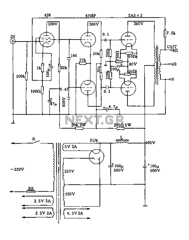
FIG. 2A3A is a low direct thermal resistance transistor with a resistance of only 800 ohms. The output transformer has a primary screen to load impedance of 3.5k ohms. The push-pull amplifier tube operates with a screen voltage ranging...
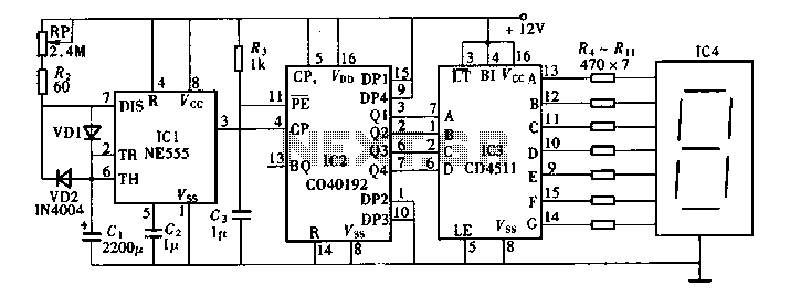
Digital timers feature a clear and precise display. They represent time intervals based on pulse signals, which are decoded by a digital device with a digital display unit. The circuit described pertains to a digital display for these timers,...
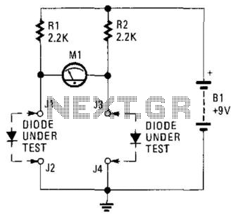
This circuit can be utilized to match diodes for applications where balance is essential, such as in a balanced modulator. The diode matching circuit will display the forward voltage drop of the two diodes in millivolts. The diode matching circuit...
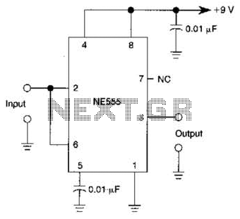
A 555 IC is configured to function as a Schmitt trigger. Inputs above and below the threshold level will turn the circuit on and off, producing a square wave output. The 555 timer integrated circuit (IC) is a versatile device...
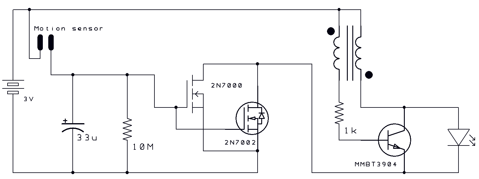
Two thoughts on a motion-activated Joule Thief LED bike light. The circuit for switching on and delayed switch-off is simple. The motion-activated Joule Thief LED bike light utilizes a straightforward circuit design that capitalizes on the principles of energy conservation...
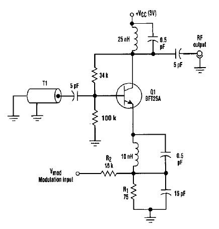
This varactorless high-frequency modulator electronic project must be powered by a simple DC 3-volt power source, such as a 3-volt battery. Traditionally, high-frequency oscillators are frequency-modulated using a varactor. However, varactors typically require a significant voltage change to achieve...