
Motion activated joule thief circuit
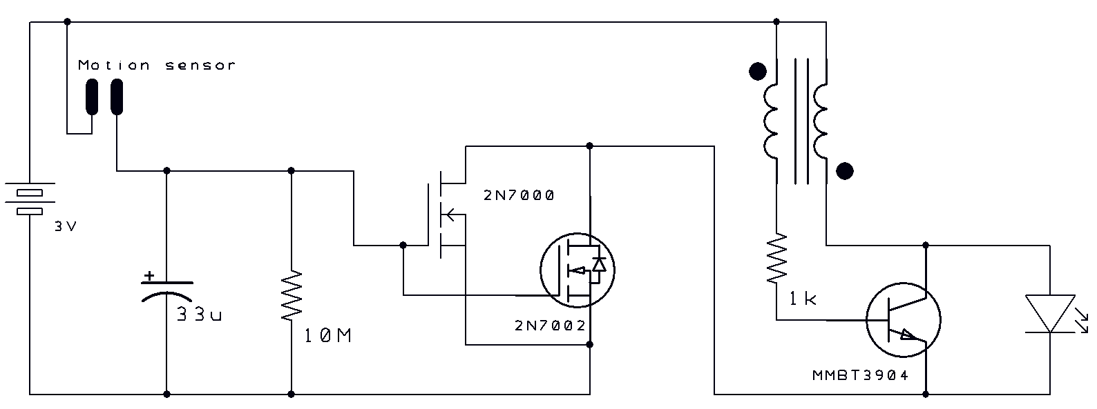
The motion-activated Joule Thief LED bike light utilizes a straightforward circuit design that capitalizes on the principles of energy conservation and efficient power usage. The Joule Thief circuit is a low-power boost converter that allows for the use of energy from depleted batteries, making it ideal for applications where power sources are limited.
The motion detection component typically employs a passive infrared (PIR) sensor or a similar device that detects movement within a specified range. Upon detection of motion, the circuit activates the LED light, providing illumination for safety during nighttime cycling. The design includes a delayed switch-off feature that keeps the light on for a predetermined period after motion ceases, enhancing visibility and safety for the user.
The circuit consists of a few key components: a power source (usually a low-voltage battery), a Joule Thief circuit that includes a transistor, a resistor, and an inductor, as well as the LED itself. The PIR sensor or motion detector is integrated into the circuit to control the activation and deactivation of the LED.
When the motion sensor detects movement, it sends a signal to the Joule Thief circuit, enabling it to draw power from the battery and illuminate the LED. The delayed switch-off mechanism can be achieved using a capacitor that holds the charge momentarily, allowing the LED to remain lit for a short duration even after the motion has stopped.
This design not only maximizes battery life but also ensures that the bike light is functional only when needed, providing an efficient and practical lighting solution for cyclists.","2 thoughts on Motion activated joule thief led bike light. The switch-on and delayed switch-off circuit is simple. 🔗 External reference
Related Circuits
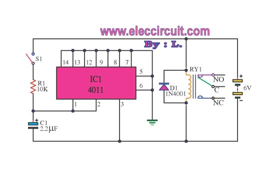
This circuit illustrates the use of the 4011 integrated circuit (IC) for a surge protection electronic circuit diagram. Features include the ability to delay the activation of other appliances connected to the output. The 4011 IC is a quad 2-input...
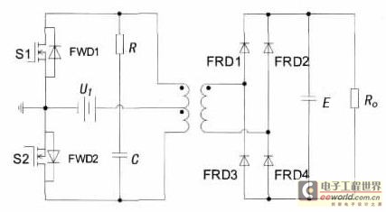
With the increase in the variety of modern electrical equipment for vehicles and the rise in power levels, there is a growing demand for different types of power supplies, including AC and DC sources. The power system needs to...
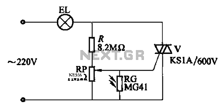
An automatic light control circuit is designed to illuminate a lamp when it is dark and to turn off the light at daybreak. The circuit, as shown in Figure 2-86, employs bidirectional thyristor tubes and features a straightforward design....
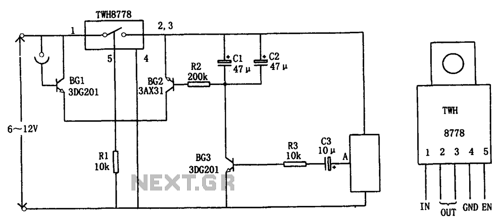
The circuit illustrated in FIG X pertains to automatic circuitry for US recorders. It primarily utilizes a new power switching device, TWH8778, which simplifies the design and eliminates the need for extensive debugging. The TWH8778's configuration and pin functions...
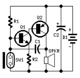
The system involves positioning a small magnet near the stalk switch SW1, which is connected to the hand or garments of the individual carrying the bag via a tiny cable. Due to the compact nature of the circuit, it...
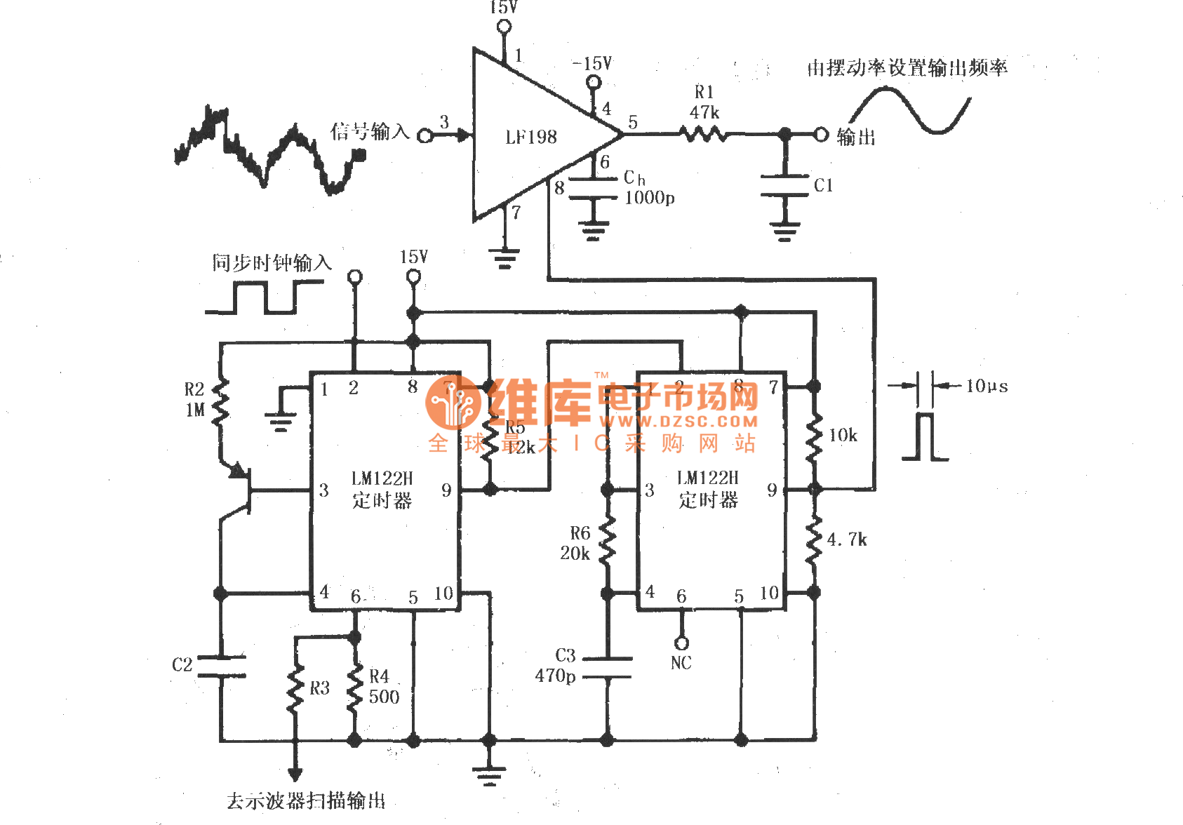
A synchronous clock signal is fed into a cascade of timer circuits composed of two LM122H devices. The synchronization clock is then converted into a pulse of the desired width, which is added to the LF198 logic end (pin...