
Siren

The circuit design incorporates an LM389 transistor, which serves as a critical component for switching the power amplifier on and off. This is achieved through a muting technique that effectively silences the amplifier when necessary, preventing unwanted noise or signal interference during idle periods.
The cross-coupled multivibrator circuit is constructed with complementary transistors that provide a stable oscillation. This configuration allows for the generation of a square wave, an essential waveform for various applications, including signal modulation and clock generation. The oscillation frequency can be finely tuned using potentiometer R2B, which is connected in such a way that it adjusts the timing components of the multivibrator, thereby altering the frequency of the output square wave.
The output from the power amplifier, acting as a square-wave oscillator, can be utilized in various applications, including driving speakers or other components that require a pulsed signal. The ability to adjust the frequency with R2B offers flexibility in the circuit's performance, accommodating different operational needs or specific requirements for the application at hand.
Overall, this circuit represents a versatile design that combines muting capabilities with precise frequency control, making it suitable for use in audio applications, signal processing, and other electronic systems where modulation and control of signals are critical.This circuit uses one of the LM389 transistors.to gate the power amplifier on and off by applying the muting technique. The other transistors form a cross-coupled multivibrator circuit that controls the rate of the square-wave oscillator.
The power amplifier is used as the square-wave oscillator with individual frequency adjust provided by potentiometer R2B.
Related Circuits
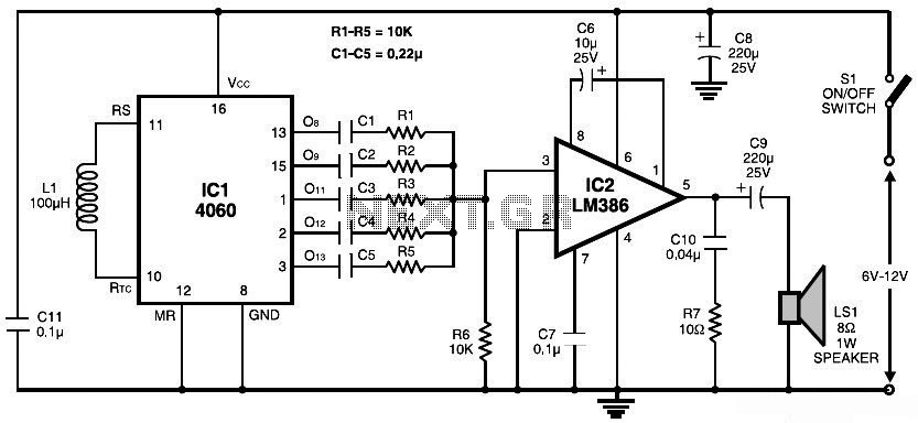
This document presents a simple schematic of a multitone siren alarm circuit. The multitone siren is effective for reverse horns, burglar alarms, and various other applications. It generates five distinct audio tones, making it significantly more attention-grabbing than a...
Utilizes a 5558 dual operational amplifier and four general-purpose NPN transistors to generate a triangle wave. This wave can be distorted using a 10k symmetry control, allowing for either a fast or slow rise time for the sawtooth waveform...
The circuit was designed to create an electronic siren to produce an alert sound in emergency situations or any circumstances that require its usage. The 4011 is a quad 2-input NAND gate integrated circuit, characterized by minimal voltage supply...
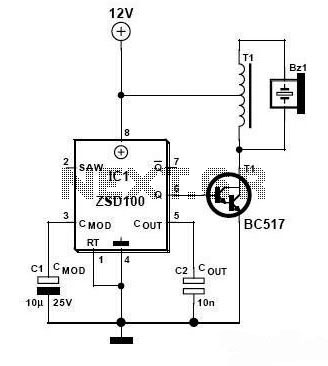
Zetex Semiconductors offers a siren driver integrated circuit (IC) known as the ZSD100, which is designed for use in alarm systems for vehicles and model crafts. By incorporating just a few additional components, as illustrated in the accompanying diagram,...
This is a police tone circuit for a siren. It is simple and easy to construct. VR1 and VR2 are used to adjust the delay of the siren sound. The design is straightforward and uncomplicated. The police tone siren circuit...
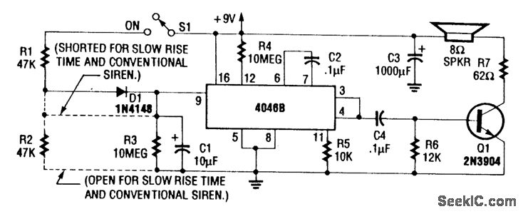
For a normal wailing tone, short D1 and leave R2 open. To achieve a fast rise and slow fall in frequency, include both D1 and R2. Utilizing a CD4046B with a diode-RC network as illustrated generates a siren tone...