
siren 100db

The circuit employs a piezoelectric sound generator, which is designed to emit a high-decibel sound that can effectively deter intruders. The primary function of the piezo element is to produce a loud, attention-grabbing noise when activated, making it difficult for a potential robber to remain in the vicinity without being alerted to the presence of others.
In this configuration, the piezo element is connected to a simple trigger mechanism, which can be activated by various sensors, such as motion detectors or pressure switches. When the sensor detects movement or pressure, it completes the circuit, allowing current to flow to the piezo element, thus generating the loud sound.
The circuit design omits the "F" contact, which is typically used for feedback in more complex circuits. This simplification reduces the number of components required and streamlines the design, making it easier to implement and maintain.
Power supply considerations are essential for this circuit, as the piezo element requires sufficient voltage to produce the desired sound level. A battery or a low-voltage power supply can be utilized, depending on the application and the required portability of the device.
Overall, this circuit serves as an effective security measure, leveraging the psychological deterrent of loud noise to prevent unauthorized access and enhance safety.A robber will not stay anywhere with an ear-piercing sound as he cannot hear if someone is approaching. It`s the best deterrent you can get. The "F" contact on the piezo is "feedback" and is not needed in this circuit. 🔗 External reference
Related Circuits

This is a compact electronic siren circuit based on three transistors. This circuit is suitable for incorporation with other alarm or siren projects such as burglar alarms, automatic factory sirens, or a simple push-to-on alarm. The electronic siren circuit...
This circuit features a two-tone siren integrated within a single IC. It is designed for children's entertainment and can be installed on bicycles, car battery chargers, and other applications. The two-tone siren circuit utilizes a single integrated circuit (IC) to...
A complementary transistor pair (Q2 and Q3) is configured as a high-efficiency oscillator that directly drives the loudspeaker. Q1 is responsible for fully charging capacitor C2 when power is applied to the circuit. When switch P1 is pressed, C2...
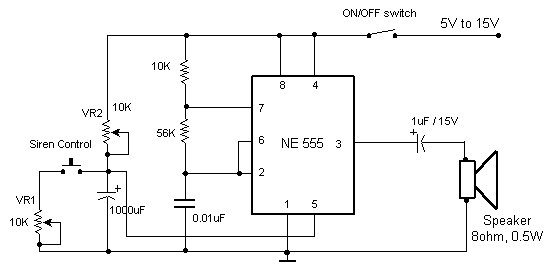
The circuit diagram of an electronic siren based on the NE555 timer produces a sound similar to that of a factory siren. The NE555 timer IC functions as an astable multivibrator with a center frequency of approximately 300 Hz....

This circuit utilizes one of the LM389 transistors to control the power amplifier's operation by implementing a muting technique. The remaining transistors create a cross-coupled multivibrator circuit that regulates the frequency of the square-wave oscillator. The power amplifier functions...
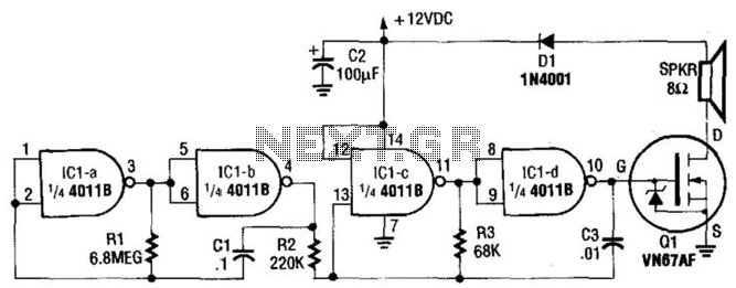
This circuit utilizes a CMOS chip and a VMOS FET amplifier to achieve 6 W of audio output. With a +24 Vdc power supply, it can generate up to 18 W of audio. IC1A and IC1B function as a...