
Siren system circuit
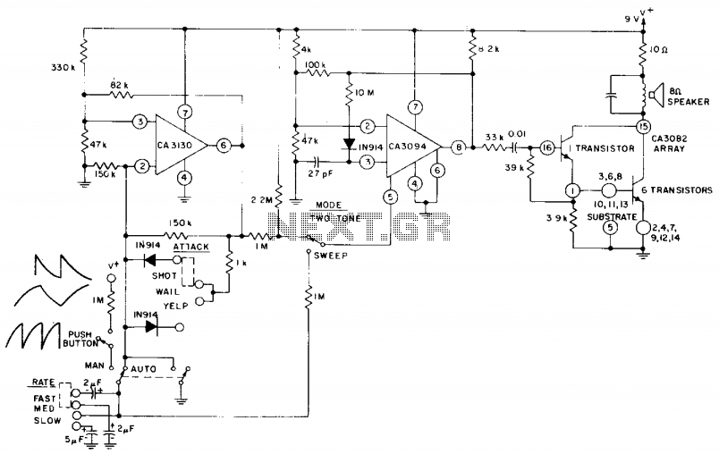
The circuit design incorporates several key components that work together to achieve the desired functionality of the siren system. The CA3130 BiMOS op-amp serves as the core of the multivibrator configuration, providing the necessary gain and stability for generating square wave signals. This output signal directly influences the siren's rate, allowing for adjustable frequency modulation based on user input.
The CA3094 voltage-controlled oscillator (VCO) is crucial for creating variable frequency outputs. It receives control voltage inputs that determine the oscillation frequency, which can be modulated by the user through the "Rate" switch. This feature allows for customization of the siren's sound pattern, enhancing its effectiveness in various applications.
The CA3082 transistor array functions as a driver stage, amplifying the signal from the VCO to a level sufficient to drive the speaker. This component ensures that the audio output is loud and clear, making the siren more effective in alerting or warning scenarios.
The inclusion of a "Manual" or "Auto" mode switch provides flexibility in operation. In "Manual" mode, the siren can be set to produce sound intermittently, while "Auto" mode allows for continuous sound output. This dual functionality is particularly useful in situations where different alerting patterns may be required.
Furthermore, the additional three switches—designated for "Mode," "Attack," and "Rate"—offer further control over the siren's performance. The "Mode" switch may allow for different sound patterns or tones, the "Attack" switch could control the ramp-up time of the sound, and the "Rate" switch adjusts the frequency of the oscillation, providing a comprehensive user interface for tailoring the siren's operation to specific needs.
Overall, this circuit design exemplifies a well-thought-out approach to creating a versatile siren system capable of meeting diverse operational requirements.The circuit uses a CA3130 BiMOS op amp as a multivibrator to control the siren's rate. A CA3094 used as a VCO is followed by a CA3082 transistor array used to drive a speaker. A "Manual" or "Auto" mode switch allows the user to select either intermittent or continuous siren operation, respectively. In addition, three switches are available that control "Mode", "Attack", and "Rate". 🔗 External reference
Related Circuits
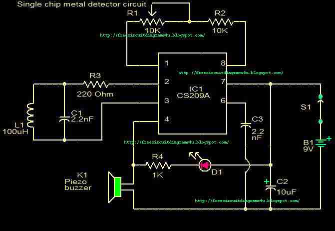
This circuit is a single chip metal detector. Actually, we can use this one to detect metals. Especially, you have seen some army soldiers keep something to detect metals. That equipment has been made through this circuit. So you...
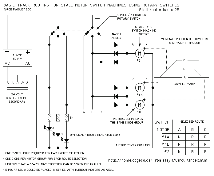
This page shows some methods of track routing control for Stall-Motor type switch machines. The principle method uses a 2 Pole - Multi Position rotary switch while an alternate uses optoisolators and transistors to select the routes. The last...
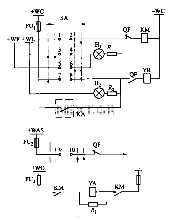
Factories and enterprises operating at voltages of 10 kV and below commonly utilize the CD10 (formerly CD2) type electromagnetic actuator as a circuit breaker. This mechanism features a mechanical anti-jump device. The control signal circuit for the CD10 actuator...
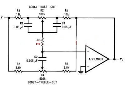
A simple tone control circuit can be designed using the LM833 operational amplifier along with a few external components. The LM833 is a dual general-purpose operational amplifier, specifically optimized for performance in audio applications. This tone control circuit utilizes...
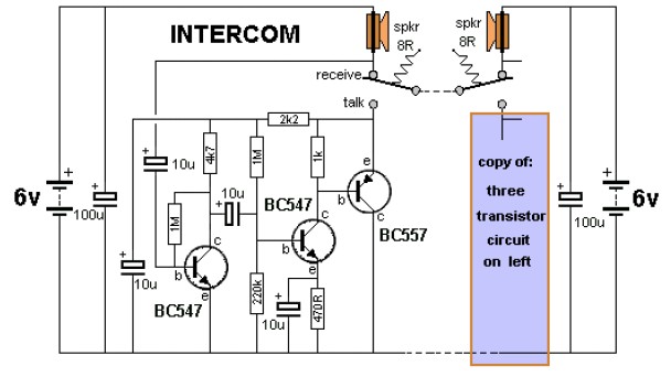
The key to avoiding instability (motor-boating) in a high-gain circuit is to power the speaker using a separate power supply. This circuit design allows for the connection of one or two additional stations. It is recommended to construct the...
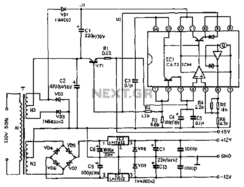
The circuit depicted features a secondary N3 center tap transformer (T) with a common point connecting diodes VD2 and VD3 to positive electrodes, along with capacitors C2, C6, C7, and negative electrodes connected to capacitors C9 and C10. Additional...