
Six-way operation of the dynamic braking circuit
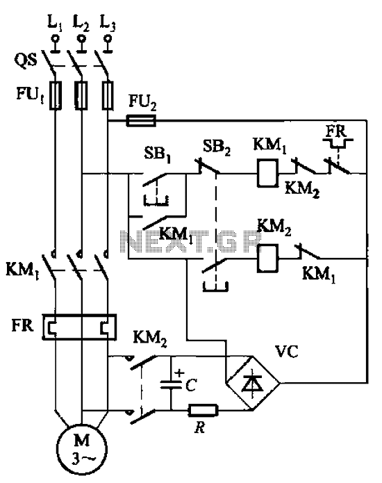
The circuit operates by employing capacitors that store electrical energy when the motor is in operation. Upon activation of the braking mechanism, the stored energy is rapidly discharged through the motor windings, creating a counteracting torque that slows down the motor. This method is efficient as it allows for quick energy release, enhancing the braking response time.
The choice of capacitance is critical; it must be sufficient to store enough energy to provide effective braking while remaining within the voltage limits of the system. Capacitors rated for voltages greater than 600V are utilized to ensure safety and reliability under high-voltage conditions. The capacitance value, typically in the range of hundreds of microfarads, is calculated based on the motor's power requirements, ensuring that the energy storage is adequate for the braking needs.
Resistance plays a vital role in controlling the discharge rate of the capacitor. Lower resistance values are preferable for higher power motors, as they allow for a quicker discharge of energy, resulting in more effective braking. Conversely, higher resistance values may be used for smaller motors to prevent excessive current that could damage the circuit components.
In summary, the circuit design integrates capacitors and resistors to provide an efficient energy storage and discharge mechanism for motor braking applications. Proper selection of capacitance and resistance values is essential to optimize performance and ensure the system operates safely and effectively. Circuit shown in Figure 3-138. The line is also using the principle of energy storage capacitors discharge achieve braking. Capacitance C and resistance R parameters from the m otor power size. Capacitance C- like hundreds of microfarads, voltage greater than 600V; R- resistance as a few tens of ohms to 100 fl (motor power greater the resistance Phi Bai small).
Related Circuits
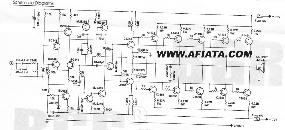
How many speakers can be attached to this amplifier, and what are the impedance and wattage values of these speakers? Please respond to my email. Sir, you made this amplifier, and it works properly for a lifetime. Which transformer...

This design circuit outlines a simple, low-cost, and ultra-compact VHF/UHF Low-Noise Amplifier (LNA) that can be implemented using the MAX2664 and MAX2665 devices, which are specifically tailored for VHF/UHF applications. The MAX2664 operates within the UHF frequency range of...
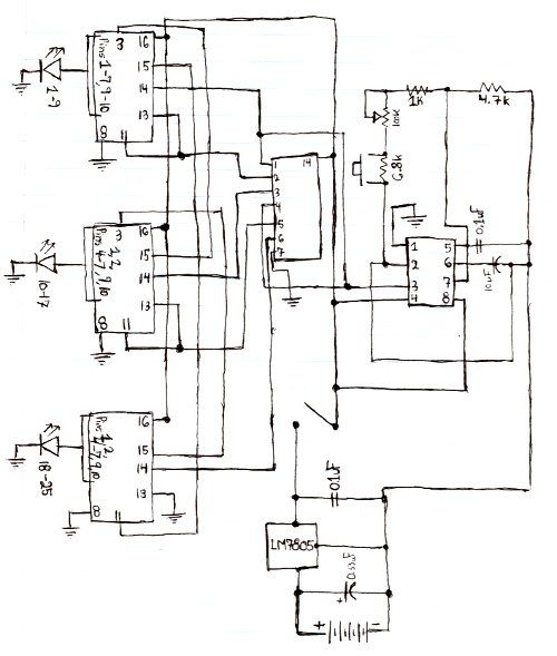
Here is the schematic for the circuit. Solder all the components onto a perfboard. The drawings may not be very clear. Essentially, the 555 timer generates a pulse. The circuit utilizes a 555 timer IC configured in astable mode, which...
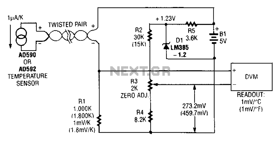
An AD590 or AD592 can be utilized in a transmission line for temperature data transmission. The circuit generates a value of 1 mV per degree Fahrenheit. The AD590 and AD592 are precision temperature sensors that output a voltage proportional to...
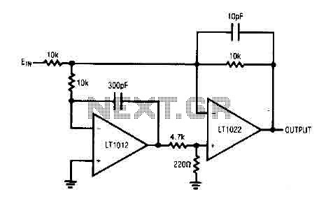
The circuit comprises a low drift LT1012 device and a high-speed amplifier LT1022. It functions as a unity gain inverter, with the summing node located at the junction of three 10k ohm resistors. The circuit monitors the summing node...
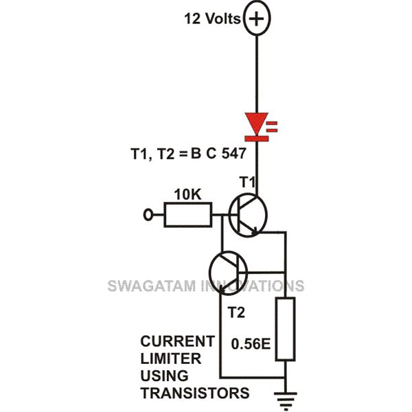
This article compiles small transistor circuits and configurations suitable for beginners, including current amplifiers, limiters, oscillators, and latches. A simple current amplifier circuit can be constructed using just a couple of NPN transistors. Additionally, two transistors and resistors can...