
Spark Transmitter Circuit

The described circuit presents a straightforward yet effective implementation of early radio communication principles, adapted for modern use. The transmitter, utilizing a piezoelectric spark mechanism, generates high-frequency electromagnetic waves when activated. The soldered brass wire acts as an antenna, efficiently radiating the generated RF energy. This simplicity in design allows for easy construction and experimentation.
The receiver's architecture employs solid-state components, enhancing reliability and performance compared to historical counterparts. The telescopic antenna is designed to maximize reception of the RF signals, while the resonant circuit ensures that the desired frequency is selectively amplified. The use of a Germanium diode for rectification is notable, as it provides low forward voltage drop, thus improving efficiency in signal processing.
The amplification stage, utilizing a Darlington configuration, enables significant signal enhancement, ensuring that even weak RF signals can be detected. The integration of a flip-flop IC allows for digital control, providing a clear on/off indication via the LED. This feature can be expanded through the use of a relay, facilitating the operation of various electrical devices, thus broadening the practical applications of the circuit.
Overall, this project not only serves as an educational tool for understanding the fundamentals of radio transmission and reception but also showcases the evolution of electronic circuit design from rudimentary components to contemporary solid-state technology. This hands-on experience can be particularly valuable for those interested in electronics, telecommunications, and the historical development of radio technology.In 1896, Marconi successfully covered a distance of about 3 km using electromagnetic waves. A little later, he established radio contact across water between Lavernock Point, South Wales and Flat Holm Island. The transmitter consisted of a spark inductor coupled to a dipole antenna. At the receiver side, he used another dipole and a glass tube filled with silver and nickel filings, the so-called coherer. The filings enabled the coherer to act as a defined` bad contact with the RF pulse energy rattling` the contact and thus driving the audio amplifiers connected to the output. The circuit shown here operates on he same principle. Admittedly it does not cover the same distance as Marconi`s extensive radio equipment, but then you do not need to start filing away on the family`s silver cutlery!
The transmitter consists of an empty (!) disposable cigarette lighter with a piezo spark mechanism. On the gas nozzle of the empty lighter you solder a 30-cm long, 1-mm diameter (20 SWG) solid brass wire which acts as an antenna. When the spark button is pressed, the antenna briefly radiates electromagnetic energy in the VHF FM frequency band.
The effect is easy to verify by holding the transmitter close to an FM radio and firing` it! Compared with the primitive transmitter, our receiver is a more up to date design realised in all solid-state` electronics. A telescopic antenna picks up the transmitter`s RF energy and applies it to a resonant circuit consisting of an inductor and a capacitor.
The electrical signal is rectified by a Germanium diode (AAxxx or OAxx) and amplified by a darlington stage. The collector of the second transistor causes voltage changes at pin 4 of the bistable (flip-flop) IC type 4013.
The receiver sensitivity can be adjusted using preset P1. Each time the transmitter sparks away, the flip-flop toggles and switches the LED on or off. As a circuit variation, you may want to use a relay instead of a LED to allow lamps, a TV set, motors or actuators to be switched on and off using your primitive` spark transmitter. Your friends will be impressed. 🔗 External reference
Related Circuits
A larger version of the circuit diagram can be accessed by clicking here. The circuit was created using Eagle from CadSoft, which is a free schematic and PCB layout software for small non-commercial projects. The core component of the...
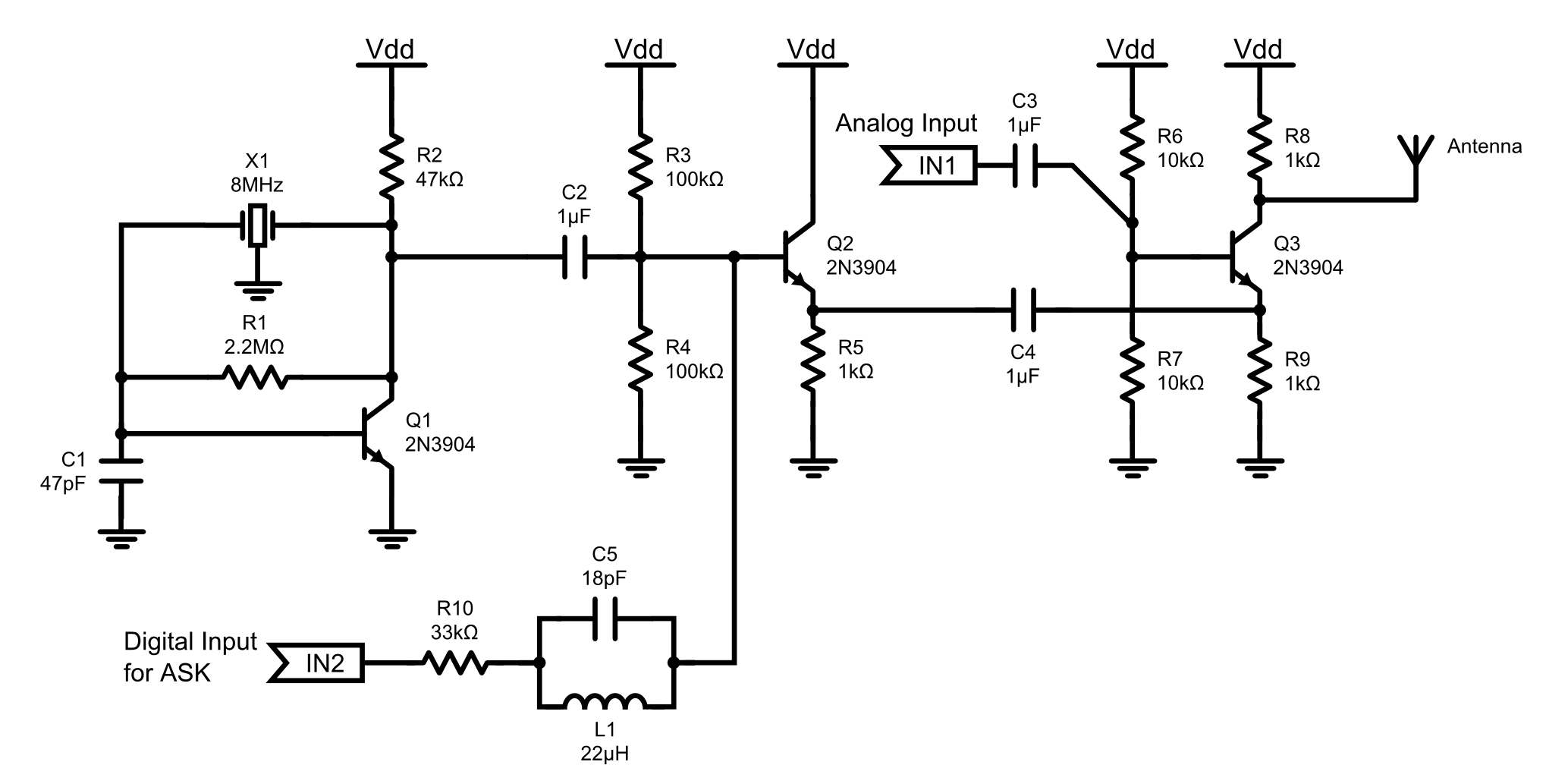
This is an 8MHz amplitude modulated (AM) radio transmitter designed primarily for work purposes and as an exercise in electronics. It serves as a simple radio transceiver that may be utilized for various future projects. The 8MHz AM radio transmitter...

This compact FM transmitter has a range of approximately 50 meters and is designed for hobbyists. With multiple mini-transmitters, users can create a diverse and engaging radio program. The device achieves high frequency stability due to its power supply...
When the doorbell switch K1 is pressed, the doorbell rings and LED D3 lights up. If there is no one to answer the door, guests will leave, but D3 remains illuminated, indicating that visitors have arrived. The circuit includes...
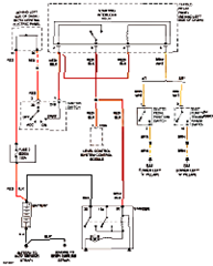
This circuit below shows an electrical circuit applicable for the Audi A4 Quattro 2004 model year. Component: Transmission, Anti-lock Brakes Circuit. The electrical circuit for the Audi A4 Quattro 2004 model year encompasses critical components such as the transmission system...

By observing the frequency at which a specific LED flashes, it is possible to estimate the resistance value. The circuit comprises two integrated circuits (ICs): a 4011 CMOS quad 2-input NAND gate (U1) and a 4024 binary counter (U2),...