
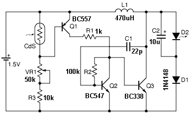
Joule Thief LED circuit 2
In electronic circuit design, adherence to standardized symbols and layout conventions is crucial for effective communication among engineers and technicians. A well-drawn schematic diagram serves as a visual representation of the circuit's functionality and interconnections, allowing for easier troubleshooting, collaboration, and documentation.
To create a circuit schematic, it is important to utilize established symbols for components such as resistors, capacitors, diodes, transistors, and integrated circuits. Each symbol conveys specific information about the component's function, orientation, and electrical characteristics. For instance, a resistor is typically represented by a zigzag line or a rectangular box, while a capacitor is shown as two parallel lines or a pair of curved lines, depending on the type.
The layout of the circuit should follow a logical flow, often from left to right or top to bottom, which helps in understanding the signal path and power distribution. Connections between components should be clearly indicated with lines, and junctions must be marked where multiple lines intersect, usually with a dot to signify a connection or a break to indicate that the lines do not connect.
Labeling components with reference designators (e.g., R1 for the first resistor, C1 for the first capacitor) further enhances clarity. Additionally, including values for each component, such as resistance in ohms or capacitance in farads, aids in the accurate reproduction of the circuit.
In summary, the proper use of universally recognized symbols and conventions in circuit schematics is vital for ensuring that the design can be easily interpreted and implemented by others in the field. This practice not only facilitates the design process but also promotes collaboration and reduces the likelihood of errors in circuit construction and analysis.Thats why you have to draw a circuit using a placement and CONVENTION that everyone recognises. 🔗 External reference
Related Circuits

This is the simplest single transistor FM wireless transmitter circuit ever posted in CircuitsGallery. In the field of telecommunications, frequency modulation (FM) transmits information by altering the frequency of a carrier wave based on the message signal. FM utilizes...

A gyrator is a circuit that utilizes active devices and transistors to emulate an inductor. In this instance, the gyrator comprises a transistor in conjunction with resistors R1, R3, and capacitor C2. Alternatively, a unity gain operational amplifier could...

The advantage of these compact Xbee modules is that they handle most of the complex tasks. The transmitter and receiver circuits are both straightforward. The primary components in the circuit include the Xbee Modules, PIC 18LF452, and LM317. Both...

The audio circuit depicted in the figure is commonly utilized in color television systems. The pin functions and reference voltages for the TA8218AH are as follows: Pin 1: 1.9V - inverting input; Pin 2: 2.1V - R-channel audio signal...
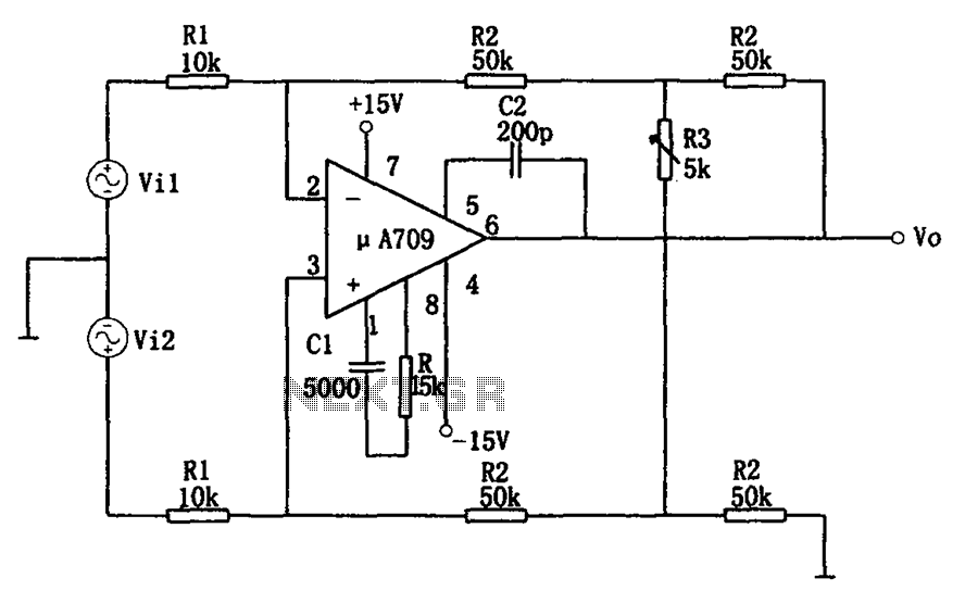
The configuration of the variable gain A709 differential amplifier circuit is illustrated. The primary advantage of this circuit is its ability to maintain a constant common-mode rejection ratio (CMRR) while allowing for continuous adjustments to the differential gain. The...

The cause may be dry solder joints, defective LEDs, or a flat battery (possibly due to a stuck key). The human eye cannot perceive infrared light, while a standard phototransistor such as the BP103 operates effectively in the infrared...
Warning: include(partials/cookie-banner.php): Failed to open stream: Permission denied in /var/www/html/nextgr/view-circuit.php on line 713
Warning: include(): Failed opening 'partials/cookie-banner.php' for inclusion (include_path='.:/usr/share/php') in /var/www/html/nextgr/view-circuit.php on line 713