
Pachisi Game Circuit
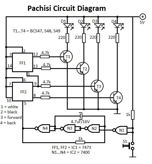
The Pachisi game, often referred to as the "Royal Game of India," is a traditional board game that incorporates elements of strategy and chance. The game board is typically cross-shaped, with each arm representing a player's path. Each player starts with a single figurine positioned at their respective starting point, marked by arrows that guide movement.
The objective of the game is to navigate the figurine around the board and reach the home space, which is located at the center of the cross. Players take turns rolling a set of dice, which dictate the number of spaces a figurine can move. The movement is not linear; players must strategically decide when to move forward or when to block opponents.
The game includes special squares that may offer advantages, such as safe zones where players cannot be captured, or bonus moves that allow for additional movement. Capturing an opponent's figurine sends it back to their starting position, adding a layer of competition and strategy to the gameplay.
To enhance the game's experience, a well-designed electronic schematic could be developed, incorporating sensors to detect player moves, LED indicators to highlight active players, and sound effects to simulate dice rolling. Such a design would require microcontrollers to manage the game state, and a user interface that displays player positions and game status. Power supply considerations would also be necessary to ensure consistent operation throughout gameplay.Pachisi game is designed for two persons. Each player has one figurine; the figurines are found in the early game on positions indicated by arrows. The goa.. 🔗 External reference
Related Circuits
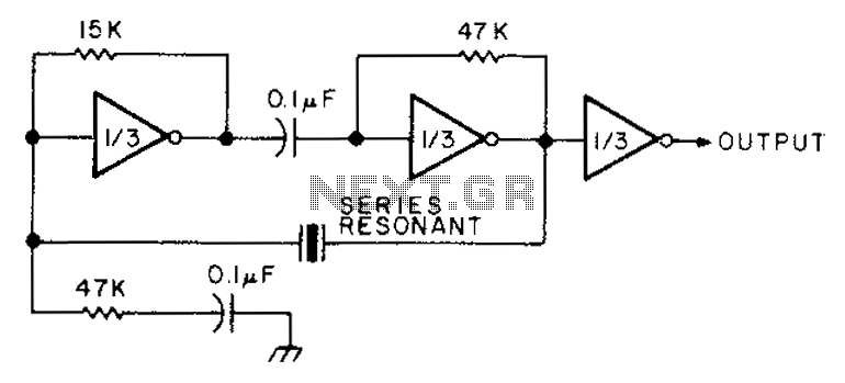
The circuit diagram illustrates the connection of all three components of the series resonant crystal and triple CD4049 inverter. The supply voltage range is between 3 to 15 volts, making it suitable for various applications. This design is compact...
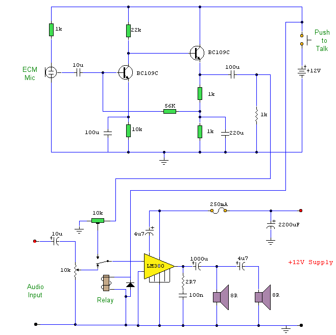
This circuit prioritizes a microphone and preamplifier (voice circuit) over any other audio signal, functioning similarly to a one-way intercom. When the push-to-talk switch is activated, the main amplifier switches from music to the voice signal. Essentially, a voice-over...
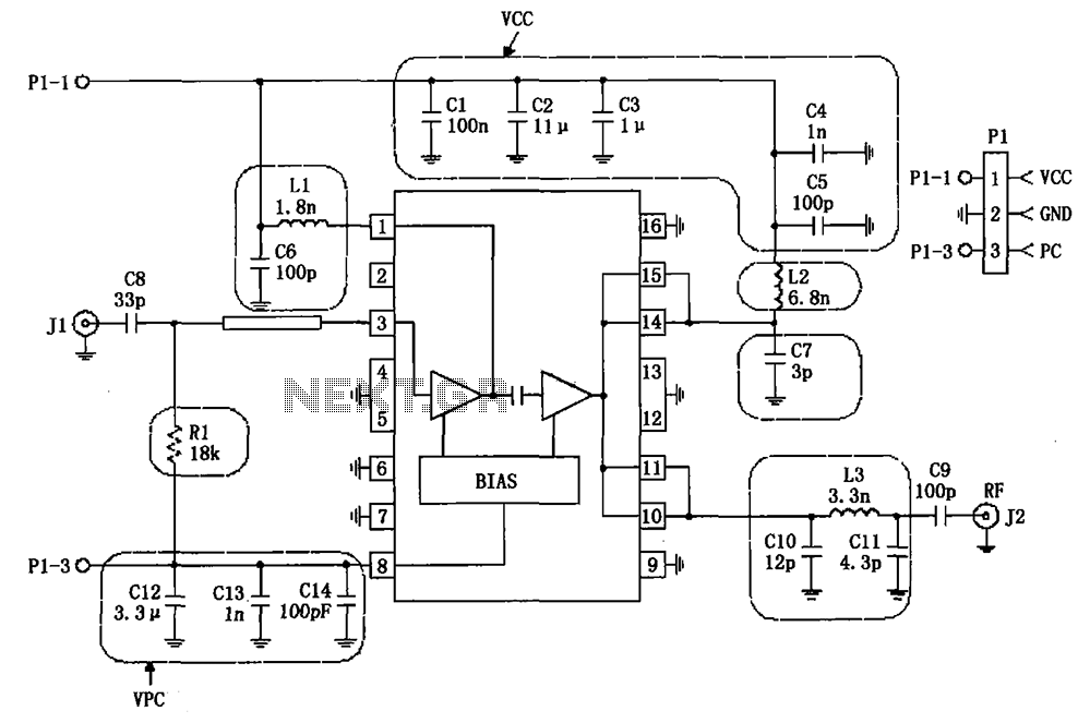
The RF2132 linear power amplifier circuit is depicted in the provided figure. A radio frequency (RF) signal enters through input pin 3 and is processed via a preamplifier. The final stage of the amplifier outputs a gain of 10....
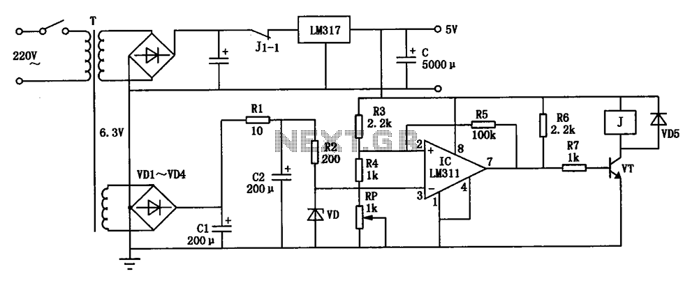
The circuit depicted can be utilized to operate at a voltage of +5V for Single Board Computer (SBC) power, preventing damage caused by over-voltage from the power supply throughout the SBC. This circuit serves as a protective mechanism for Single...
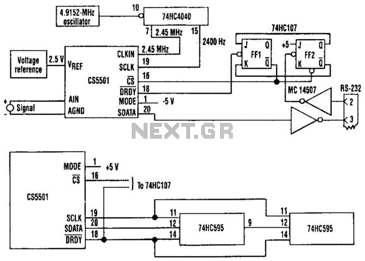
The CS5501 16-bit delta-sigma analog-to-digital converter continuously converts signals, outputting conversion words to its output register every 1024 cycles of its master clock, as it lacks a start convert command. By integrating a standard dual J-K flip-flop into the...
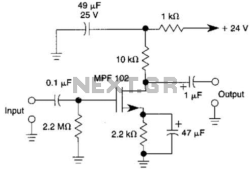
This JFET preamplifier has a gain of approximately 20 dB and a bandwidth exceeding 100 kHz. It is useful as a low-level audio amplifier for high-impedance sources. The described JFET (Junction Field Effect Transistor) preamplifier is designed to amplify low-level...