
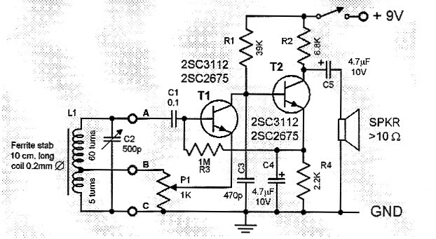
Small FM Radio Circuit
The FM radio receiver circuit typically consists of several key components that work together to demodulate the frequency-modulated signals transmitted by local radio stations. The main components of this circuit include an antenna, a radio frequency (RF) amplifier, a mixer, a local oscillator, an intermediate frequency (IF) amplifier, a demodulator, and an audio amplifier.
The antenna captures the radio signals, which are then amplified by the RF amplifier to improve the signal strength. The amplified signal is fed into the mixer, where it is combined with a signal from the local oscillator. This mixing process produces an intermediate frequency that is easier to process than the original RF signal.
The IF amplifier further boosts the intermediate frequency signal, which is then passed to the demodulator. The demodulator extracts the audio information from the modulated carrier wave, converting it into an audio signal that can be amplified by the audio amplifier. Finally, the audio output can be connected to a speaker or headphones for listening.
The simplicity of this FM radio receiver design makes it accessible for hobbyists and beginners in electronics, while still providing reliable performance for receiving FM broadcasts. The compact size allows for easy integration into various devices or projects, making it a versatile choice for anyone interested in building their own radio receiver.Perhaps this is one of the simplest and smallest FM radio receiver that can receive the FM stations available locally. Its simple design makes it ideal for.. 🔗 External reference
Related Circuits

A simple metal detector circuit diagram and schematic using a single transistor and a radio. This metal detector/sensor project is easy to make and is an application of a Colpitts oscillator. The metal detector circuit utilizes a single transistor in...
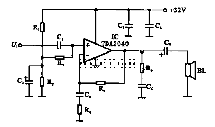
An integrated power amplifier TDA2040 is used in an OTL (Output Transformer-Less) power amplifier circuit, which operates with a +3V single supply as the working voltage. This circuit has a voltage gain of 30 dB (approximately 32 times magnification),...
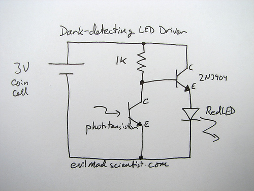
The following circuit illustrates a simple and inexpensive dark-detecting LED circuit. Features include the use of photoresistors, specifically a photocell or LDR, and an LED. This circuit utilizes a light-dependent resistor (LDR) as the primary sensing element. The LDR exhibits...
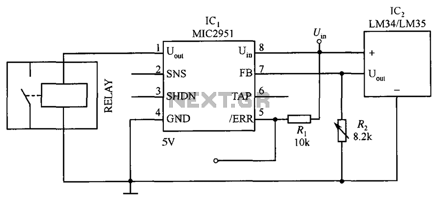
The circuit depicted in the figure utilizes a thermal protection system featuring the MIC2951 component. The temperature threshold can be adjusted by modifying resistor R2. The thermal protection circuit employing the MIC2951 is designed to monitor and regulate temperature within...

A negative output voltage DC to DC converter generates a -5V output at pin A. To achieve -5V at point A, the primary of the transformer must fly back to a diode drop more negative than -5V. If the...
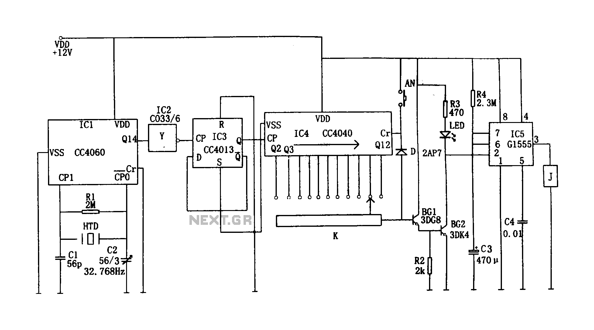
This circuit illustrates a precision digital timing control system. The controller includes a crystal oscillator circuit, a divider, a counting circuit, and monostable flip-flops. The crystal oscillator circuit features a series of 14 binary counters/dividers, a watch crystal operating...