
SmartCap solar engine
In this diagram, the "SmartCap" is just the 1.5 F storage capacitor, phototransistor, 2N3906 transistor, and 5.1K bias resistor. The idea is that after charging, a loss of light causes the 1.5 F capacitor to be discharged through the 75 Ohm resistor -- this gives the photopopper a sudden "recharge," which it can use to get to a brighter spot.
The "Vore-N-More" circuit is designed to utilize solar energy efficiently, employing a SmartCap solar engine that integrates several key components to achieve its functionality. The primary component, the 1.5 F storage capacitor, serves as a reservoir for electrical energy harvested from sunlight. This capacitor is charged during periods of adequate light exposure, allowing it to store energy that can be utilized when light levels drop.
The circuit includes a phototransistor that acts as a light sensor. When ambient light levels decrease, the phototransistor detects this change and triggers the discharge of the stored energy from the capacitor. The 2N3906 transistor functions as a switch to control the flow of current from the capacitor. It is activated by the phototransistor's output, allowing the energy to be released through a 75 Ohm resistor. This rapid discharge creates a brief surge of power, referred to as a "recharge," which can energize the photopopper mechanism.
The 5.1K bias resistor is critical for setting the operating point of the phototransistor, ensuring it responds appropriately to changes in light intensity. This configuration allows the circuit to react dynamically to its environment, enabling the photopopper to move toward areas of higher illumination effectively.
Overall, the "Vore-N-More" circuit exemplifies an innovative approach to energy management in solar-powered devices, utilizing simple yet effective electronic components to create a responsive system that maximizes the use of available light.Here`s a circuit diagram (originally drawn by Wilf Rigter, I corrected it based on Bob`s on-list feedback) for Bob`s "Vore-N-More" circuit containing the SmartCap solar engine: In this diagram, the "SmartCap" is just the 1.5 F storage capacitor, phototransistor, 2N3906 transistor, and 5.1K bias resistor. The idea is that after charging, a loss of light causes the 1.5 F capacitor to be discharged through the 75 Ohm resistor -- this gives the photopopper a sudden "recharge," which it can use to get to a brighter spot.
🔗 External reference
Related Circuits
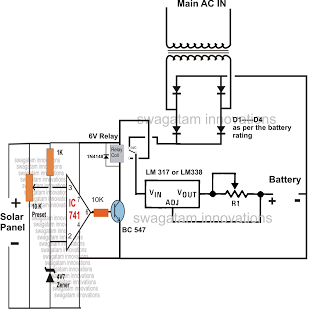
The automatic changeover relay circuit was requested by Mr. Karimulla Baig. The circuit is designed to charge a connected battery at a constant current using power from a solar panel. In the absence of solar energy, such as during...
How would you use an SE with a chip enable? Good question and well one thing leads to another and before you know it a new solar roller is born. The design started out as a simple example of...
Savings on electricity bills can be achieved by utilizing alternative power sources. The photovoltaic module, or solar panel, described here can provide a power output of 5 watts. Under full sunlight conditions, the solar panel generates an output voltage...
Construct a low-cost and relatively simple robot that activates whenever a desk lamp is illuminated. The design does not incorporate any sensors. This robot can be designed using basic electronic components to create a simple activation mechanism based on light...
Schematic of an automatic solar garden light circuit with 10 super bright white LEDs that will automatically activate at night. The automatic solar garden light circuit is designed to harness solar energy for illumination purposes during nighttime. The circuit typically...
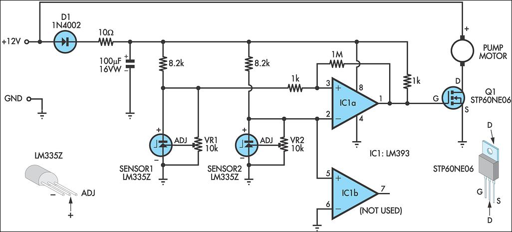
A solar water heating pump controller is an essential component in most solar water heating systems, whether DIY or commercially produced. Its primary function is to activate the pump when the fluid in the solar panel is at a...