
Solar Water Heating Pump Controller
The solar water heating pump controller circuit operates by utilizing two LM335Z temperature sensors to monitor the temperatures of the solar panel and the hot water tank. The LM393 comparator chip continuously compares the voltage outputs from these sensors, which correspond to their respective temperatures. The output from the comparator is connected to the gate of an STP60NE06 MOSFET. When the temperature of the solar panel exceeds that of the hot water tank, the voltage from Sensor 1 becomes greater than that from Sensor 2, triggering the comparator to output a high signal. This high signal activates the MOSFET, allowing current to flow from the power supply to the pump, thereby initiating the transfer of hot water from the solar panel to the hot water tank.
In terms of component selection, the LM335Z sensors are preferred for their linear voltage output with respect to temperature changes, making them suitable for precise temperature measurements. The LM393 comparator is chosen for its low power consumption and ability to operate with a single supply voltage, making it ideal for solar applications. The STP60NE06 MOSFET is selected for its capability to handle high currents, which is essential for driving the pump effectively.
The circuit design should ensure proper placement of the temperature sensors to avoid exposure to water, which could damage them. Sensor 1 should be securely attached to the solar panel's outlet pipe, while Sensor 2 should be insulated on the hot water tank. Additionally, the use of variable resistors allows for fine-tuning of the system, although it can be simplified by selecting sensors with closely matched outputs. Overall, this solar water heating pump controller provides an efficient and reliable solution for managing the temperature-driven operation of solar water heating systems, ensuring optimal performance and energy savings.A solar water heating pump controller is a key component in most solar water heating systems (DIY or otherwise). The controller is there to turn the pump on when the fluid in the solar panel is hotter than the water in the hot water tank (or swimming pool), and keep it turned off at all other times.
First of all, it is worth noting that there are solar hot water system designs for which a controller is not required. The most common is Thermosyphon Solar Water Heating in which the natural rising of hot water (and sinking of cold water) is used to circulate hot water from the panel to the hot water tank, and cold water from the bottom of the hot water tank back around to the panel. It is also possible to connect a Photovoltaic Solar Panel directly to a low voltage pump - as long as the panel and pump have similar power ratings - so the pump only runs when the sun is shining.
The problem with this is that early in the morning the pump may send the previous day`s hot water from the tank to be cooled through the still cold solar water heating panel, and in the evening when the panel may be hotter than the contents of the tank, the pump will not run. The preferred system for most is to fit temperature sensors to the outlet from the solar water heating panel and to the hot water tank, and have an electronic differential temperature thermostat decide whether the pump should be turned on.
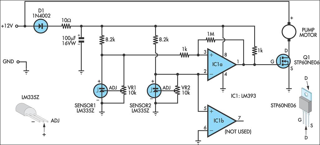
This is a solar water heating pump controller. Pictured above is the solar water heating pump controller we first started selling back in 2006 (and still sell here: basic solar pump controller to this day). It has also been made by many of our site visitors following the plans below. This circuit is made up of just a few components. Key are the two temperature sensors ( LM335Z ) which are used to measure the temperatures of the solar panel and the water tank, and the comparator chip (LM393) which compares the two temperature readings.
An STP60NE06 MOSFET (a type of transistor ) is used to switch on the pump when triggered by the output from the comparator. When the temperature of Sensor 1 (solar panel) is higher than the temperature of Sensor 2 (water tank), the 12V solar water pump is activated pumping hot water from the solar panel to the water tank as desired.
When the temperature of the water tank is higher than that of the solar panel (for example at night) the pump is off. The circuit diagram for this controller displayed above is from the Silicon Chip Online article entitled Pump Controller for Solar Water System.
(Click on the circuit diagram to view a larger printable version). The voltage measured between the ground and the positive terminals of the LM335Z increases at 10mV per °C. Since absolute zero is -273 °C, at 0 °C, the voltage measured at 0 °C is 2. 73V. At room temperature the voltage will be 273 + 20 = 2. 93 Volts etc. Since every sensor is slightly different, the circuit includes a couple of 10k variable resistors which can be used to match the voltage output of the two sensors so that they give exactly the same reading when they are at the same temperature.
Since the sensors are accurate to within 1 °C, the variable resistors (trimpots) can be left out to simplify the circuit as shown above. Simply put the sensor with the higher output voltage at a particular temperature as Sensor 2 so that when both sensors are at the same temperature, the pump will be off.
Sensor 1 should be stuck against the copper pipe as it leaves the solar panel, and Sensor 2 should be connected to the outside of the hot water tank underneath the insulation. In this way the two sensors will measure the temperature of the water pretty accurately without getting themselves wet.
(Note that water + sensor = very broken sensor) For testing purposes the two temperature sensors have been placed side by side on the breadboard, and a 12V LED Spotlight Bulb is used instead of the hot water pump. Since the 🔗 External reference
Related Circuits
A buzzer circuit utilizes a PIC microcontroller to drive a piezo buzzer. The microcontroller is a low-power processor that is ideal for portable and compact devices where battery conservation is essential. The buzzer circuit employs a PIC microcontroller, which serves...
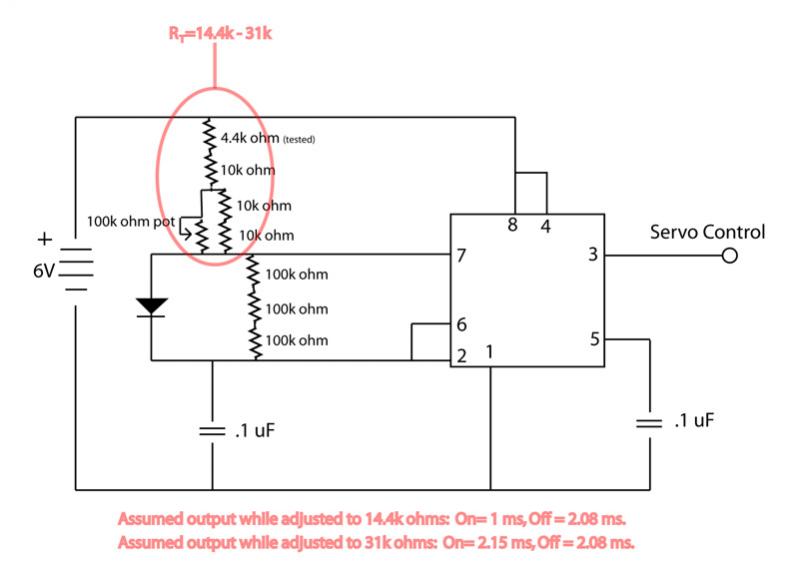
The circuit is not providing the full range of motion for a servo, only achieving approximately 90 degrees. Assistance is requested to review the circuit. To address the issue of limited servo motion, it is essential to analyze the circuit...
This article is intended for complete beginners with servo motors. It provides an overview of the basic theory behind servo motors and offers detailed instructions on how to utilize them with AVR microcontrollers such as the ATmega32. Servo motors are...
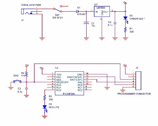
A simple program that will blink an LED. All that is required is a basic JDM programmer, and the setup is ready to go. The circuit requires a power supply, and while a good power generator is recommended, a...
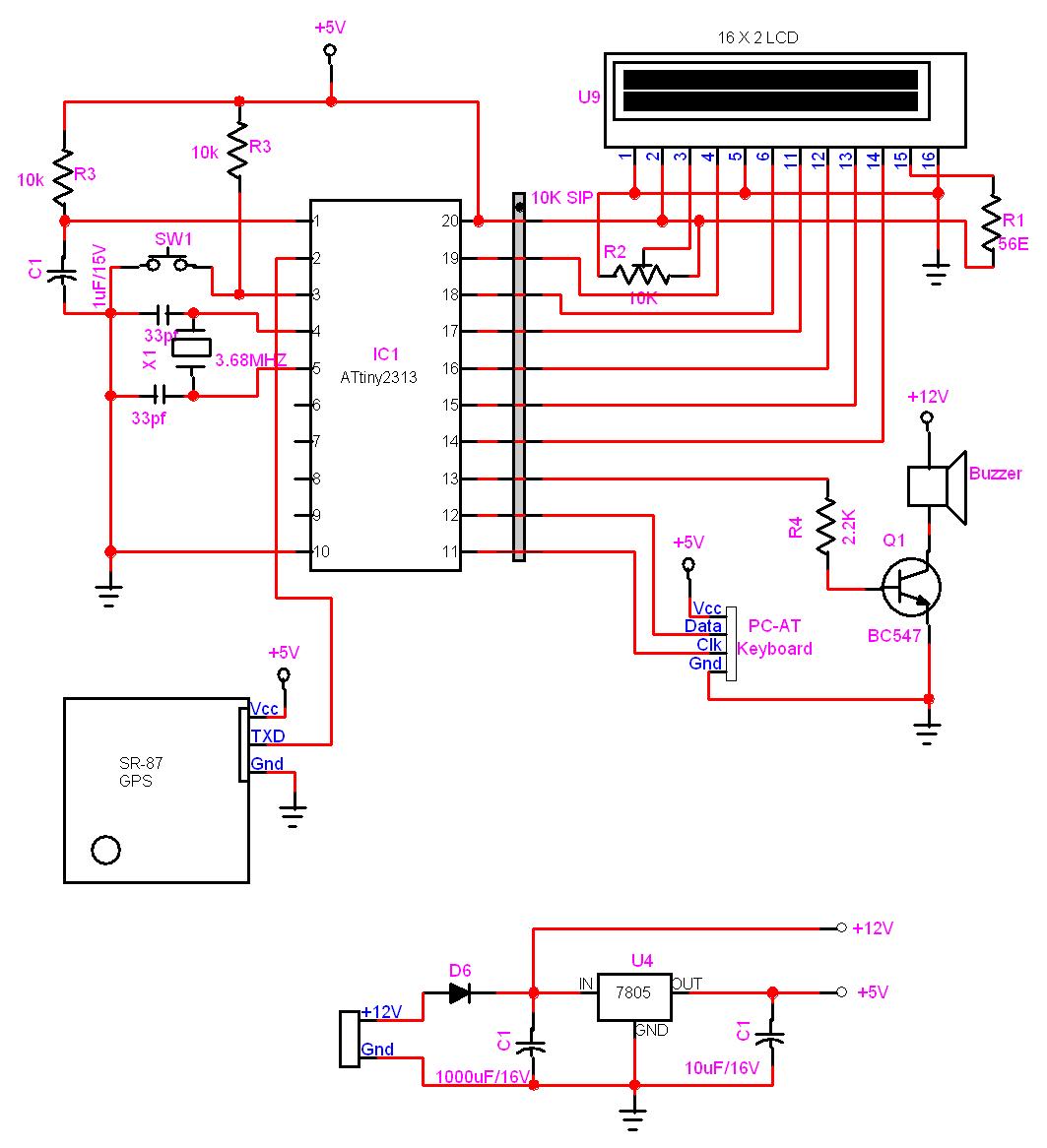
In this project, a GPS module is interfaced with an AVR microcontroller. The ATtiny2313 retrieves location data from the GPS and displays it on an LCD screen. The project involves the integration of a GPS module with the ATtiny2313 microcontroller,...
The circuit uses a 555 timer wired as an astable oscillator and powered by the emitter current of the BC109C. Under dry conditions, the transistor will have no bias current and be fully off. As the probes get wet,...