
smartcard pc cable pinout.
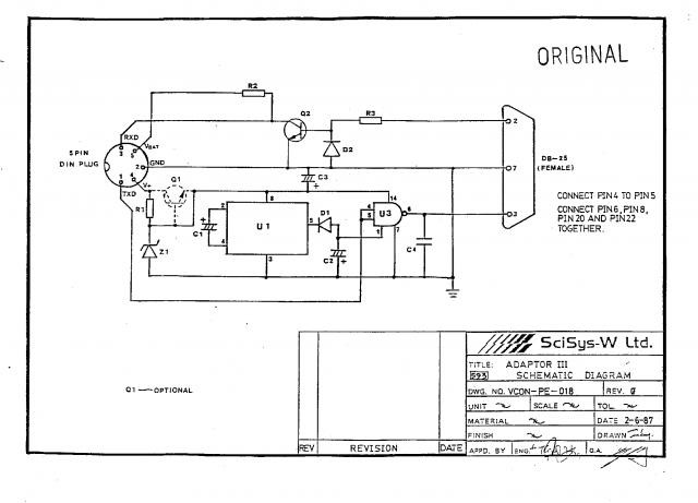
The schematic for the SIM card to PC adapter cable is essential for establishing communication between a computer and ISO 7816 compliant smart cards, which are widely used in applications such as mobile telephony and digital television services. The layout involves two primary connectors: a 6-pin connector for the SIM card and a 9-pin D-SUB female connector that interfaces with the computer.
The 6-pin SIM card connector typically includes the following pin assignments:
1. **VCC** - The power supply pin that provides the necessary voltage to the SIM card.
2. **GND** - The ground connection, which serves as the reference point for the power supply.
3. **I/O** - The input/output pin used for data communication between the SIM card and the host device.
4. **RST** - The reset pin that initializes the SIM card.
5. **CLK** - The clock signal pin that synchronizes data transmission.
6. **VPP** - The programming voltage pin, which is used for specific operations during card programming.
The 9-pin D-SUB female connector connects to the computer and typically follows the standard RS-232 pinout configuration. The relevant pins include:
1. **Pin 1 (DCD)** - Data Carrier Detect.
2. **Pin 2 (RXD)** - Receive Data, which receives data from the SIM card.
3. **Pin 3 (TXD)** - Transmit Data, which sends data to the SIM card.
4. **Pin 4 (DTR)** - Data Terminal Ready, indicating that the device is ready to communicate.
5. **Pin 5 (GND)** - Ground connection for signal reference.
6. **Pin 6 (DSR)** - Data Set Ready, indicating that the SIM card is ready to communicate.
7. **Pin 7 (RTS)** - Request to Send, used to control data flow.
8. **Pin 8 (CTS)** - Clear to Send, indicating that the device can send data.
9. **Pin 9 (RI)** - Ring Indicator, used for signaling.
The connection between the SIM card and the computer allows for the reading and writing of data to the SIM card, enabling functionalities such as contact management, SMS operations, and application management. This schematic is crucial for developers and engineers working with smart card technology, ensuring proper interfacing and communication protocols are adhered to for reliable operation. Proper attention to the pin configuration and electrical characteristics is essential to prevent damage to the components and ensure optimal performance.Pinout of Smart card (Sim card) to PC adapter cable (sim reader/writer) schematic and layout of 6 pin Simcard special connector and 9 pin D-SUB female connectorused to to connect computers to ISO 7816 compatible chip card systems (e.g. GSM mobile phones or pay-TV decoding systems).. 🔗 External reference
Related Circuits
The GS1674 is a high-speed BiCMOS integrated circuit designed to equalize and restore signals received over 75-ohm coaxial cable. The device is optimized for performance at 270 Mb/s and 1.485 Gb/s and features DC restoration to compensate for the...
You do not need access to advanced testing equipment to check and troubleshoot computer data cables. Instead, this simple device will provide a quick indication of the status. This device functions as a basic cable tester, designed to assess the...
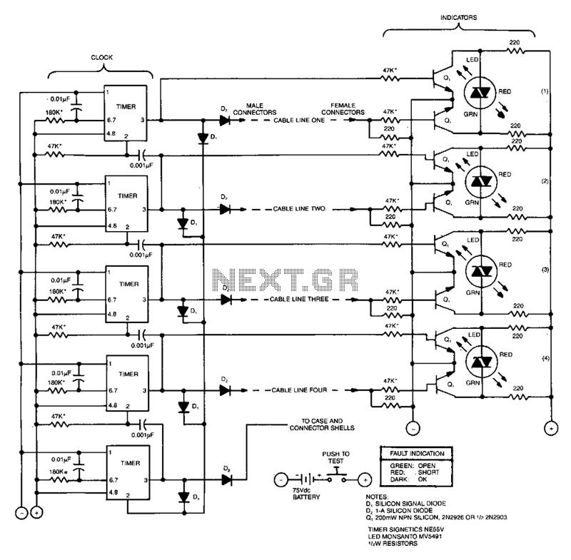
This compact tester checks cables for open-circuit or short-circuit conditions. A differential transistor pair at one end of each cable line remains balanced as long as the same clock pulse generated by timer IC appears at both ends of...
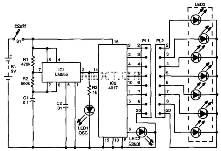
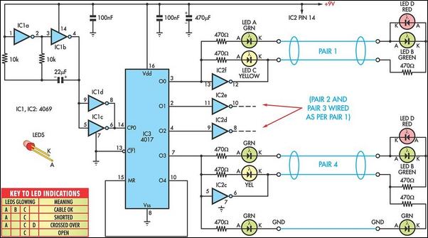
This circuit can be used to check up to an eight-conductor cable. IC1, a 555 timer, drives decade counter IC2, a 4017. Each LED should light in sequence. The cable to be tested is connected between PL1 and PL2....
The SciSys Leonardo, Saitek Galileo, and Renaissance chess computers can be connected to a PC using an OSA-Link cable, which is necessary to operate the OSA-4-Arena software and other tools. However, this cable is no longer available. Detailed instructions...
The power-supply controller features staggered voltage-output sequencing. Four voltage outputs are activated simultaneously for voltage tracking; two outputs are designated for core and I/O supplies during power-up, while the other two outputs cater to line driver supplies where tracking...
Warning: include(partials/cookie-banner.php): Failed to open stream: Permission denied in /var/www/html/nextgr/view-circuit.php on line 713
Warning: include(): Failed opening 'partials/cookie-banner.php' for inclusion (include_path='.:/usr/share/php') in /var/www/html/nextgr/view-circuit.php on line 713