
SMD FM Transmitter Circuit

The proposed low-power FM transmitter circuit utilizes surface-mount devices (SMD) to achieve compactness and efficiency. The primary components of the circuit include an oscillator, modulator, amplifier, and an antenna.
The oscillator generates a carrier frequency in the FM band, typically around 88-108 MHz, which is the standard range for FM radio transmission. A common choice for the oscillator is a Colpitts or Hartley oscillator configuration, which can be implemented using SMD transistors or integrated circuits (ICs) designed for RF applications.
The modulator section is responsible for varying the frequency of the carrier signal according to the audio input. This can be achieved using a varactor diode or an audio transformer, which modulates the frequency of the oscillator based on the audio signal's amplitude. The audio input can be sourced from various devices, such as a microphone or an audio player, ensuring compatibility with standard audio outputs.
Following modulation, an amplifier is necessary to boost the power of the RF signal before transmission. This stage can be implemented using SMD RF amplifier ICs, which are designed to operate efficiently at the desired frequency. The amplifier should be configured to provide sufficient gain while minimizing distortion, ensuring a clear signal is transmitted.
Finally, the antenna is a crucial component for effective transmission. A simple dipole or monopole antenna can be constructed using SMD components or external materials, tuned to the desired frequency for optimal performance. Proper impedance matching between the amplifier output and the antenna is essential to maximize power transfer and minimize signal loss.
Overall, this low-power FM transmitter circuit is designed with efficiency in mind, utilizing surface-mount technology to create a compact and effective device for short-range audio broadcasting.Let`s construct a low-power FM transmitter using surface-mount devices (SMD) that will be received with a standard FM radio. Soldering surface mounted devi.. 🔗 External reference
Related Circuits

My first project after assembling an electronic design lab was to build a flash trigger that I could use for high-speed photography. I thought it would be useful to share not only the finished product but also the reasoning...
This project features a schematic for a touch alarm circuit. The circuit is highly sensitive and activates a piezo buzzer or any other type of buzzer, along with an LED, for a predetermined duration when a metal plate is...

This circuit measures the distance covered during a walk. The hardware is housed in a small box that can be placed in a pocket, and the display is designed as follows: the leftmost display D2 (the most significant digit)...

In this open-loop design, the detector diode is D1, and a level-shifting or compensating diode is D2. Load resistor RL is connected to -5 V, and an identical bias resistor RB is used to bias the compensating diode, also...
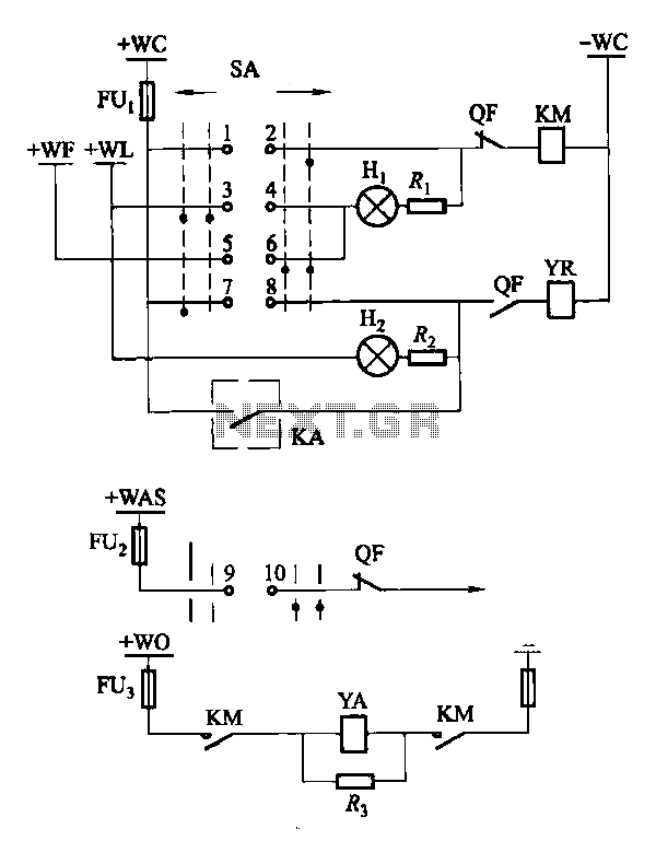
Factories and enterprises operating at voltages of 10 kV and below commonly utilize the CD10 (formerly CD2) type electromagnetic actuator as a circuit breaker. This mechanism features a mechanical anti-jump device. The control signal circuit for the CD10 actuator...

This circuit is a low-noise preamplifier designed for the 435-MHz amateur satellite frequencies. It utilizes a Mitsubishi MGF1302 transistor. A 28-Vdc power source is indicated; however, lower voltages can be employed by adjusting the 400-5-W resistor. The low-noise preamplifier circuit...