
Gasfet Preamp For 435Mhz Circuit

The low-noise preamplifier circuit operates at a frequency of 435 MHz, which is commonly used in amateur satellite communications. The choice of the Mitsubishi MGF1302 transistor is significant due to its low noise figure and high gain characteristics, making it suitable for weak signal amplification in RF applications.
The circuit configuration typically includes input and output coupling capacitors to block DC voltage while allowing AC signals to pass. These capacitors ensure that the preamplifier does not interfere with the DC biasing of subsequent stages in the signal chain. The input impedance of the preamplifier is designed to match the output impedance of the antenna, optimizing power transfer and minimizing signal loss.
Power supply considerations are crucial for the performance of the preamplifier. While a 28-Vdc source is specified, the circuit allows for flexibility in power supply voltage by incorporating a resistor that can be adjusted. This resistor, rated between 400-5 W, provides a means to lower the voltage supplied to the MGF1302, which can be beneficial in reducing power consumption and heat generation in low-power applications.
Additional components such as inductors and capacitors may be included in the design to form tuned circuits for selectivity and stability, ensuring that the preamplifier functions effectively within the desired frequency range without unwanted oscillations or interference. Proper grounding and layout techniques are essential to minimize noise and ensure reliable operation in the challenging RF environment of satellite communications. This circuit is a low-noise preamplifier for the 435-MHz amateur satellite frequencies. The circuit uses a Mitsubishi MGF1302. A 28-Vdc source is shown, although by changing the 400- 5-W resistor lower voltages can be used.
Related Circuits
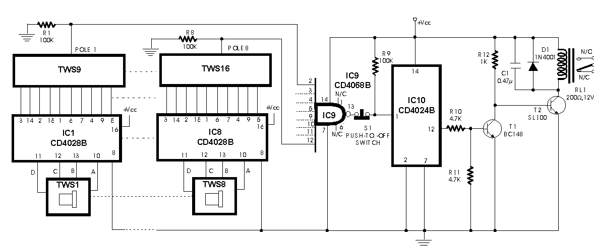
A programmable code lock can be used for numerous applications in which access to an article/gadget is to be restricted to a limited number of persons. Here is yet another circuit of a code lock employing mainly the CMOS...

A South African company has developed a 5-kilowatt Fuel Free Generator and discovered that the longevity of the batteries is significantly affected by the process. There are various types of batteries available for testing, including different lead-acid batteries, gel...
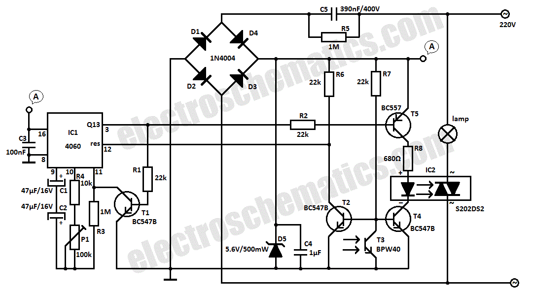
This light sensor switch circuit enables the automatic activation of a lamp when ambient light levels are low (such as during nightfall) and keeps the lamp illuminated for a specified duration. When transistors T4 and T5 are activated, the...
This design is for a thermometer circuit that utilizes the LM35 integrated circuit (IC) as a temperature sensor. It is a straightforward circuit that allows for the measurement of room temperature using a digital voltmeter or any voltmeter capable...
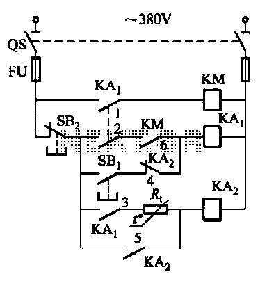
Competition among relay contacts in contactor control systems often leads to significant issues that can be cumbersome to address. In some cases, this requires the addition of numerous components. However, utilizing a negative temperature coefficient thermistor (NTC) for delay...
The impedance linear amplifier circuit is illustrated in FIG 75 and is configured using the RF2320 component. Connectors J1 and J2 are 75-ohm connectors. The impedance linear amplifier circuit designed with the RF2320 is intended for applications requiring high fidelity...