
Smoke Alarm Circuit

The updated smoke alarm circuit utilizes the LM741 op-amp as a comparator and Schmitt trigger, providing improved performance and reliability. The circuit design features a photo-interrupter that effectively detects smoke by measuring the current transfer ratio, influenced by the presence of smoke particles. The chosen H21B1 Darlington device enhances the sensitivity of the circuit, allowing for lower LED current consumption, which is critical for battery-operated devices. The integration of the Sharp GP series optical coupler ensures that the circuit remains functional with readily available components.
The operational principles of the circuit hinge on the interaction between the photo-interrupter and the LM741 op-amp. The inverting input is set to a reference voltage of 4.2V, while the collector voltage of the photo-transistor is calibrated to 4.0V. This configuration allows the circuit to detect significant changes in the collector voltage when smoke is present, triggering the op-amp to output a high signal that activates the MOSFET. The MOSFET serves as a switch, connecting the load (LED and siren) to ground, thereby signaling an alarm condition.
The inclusion of a timing capacitor (C1) in the feedback loop ensures that the alarm remains active for a brief period after the smoke has cleared, preventing false alarms from momentary fluctuations in smoke density. The choice of capacitor material is essential, as it must withstand voltage reversals without degradation. Resistor R1 plays a crucial role in adjusting the collector voltage of the photo-transistor, while R2 allows for fine-tuning based on the specific characteristics of the photo-interrupter used.
Overall, this circuit design not only addresses the shortcomings of previous smoke alarm circuits but also provides a robust and efficient solution for smoke detection, suitable for both hobbyists and educational purposes. The careful selection of components, combined with a clear understanding of operational parameters, ensures a reliable and effective smoke alarm system.The original smoke alarm circuit has some problems and has left some hobbyists and students disappointed. Rather than to attempt to solve its many problems, I have created an update that uses the venerable LM741 op amp.
It is simpler, more conventional, easier to understand and has much better battery life. The photo-interrupter is simply an opti cal coupler with the elements separated with a slot. Anything that enters this slot reduces the current transfer ratio (output current /input current). I used the H21B1 Darlington device since I did not have the H21A1 on hand. I am glad I did, because I learned that it is a better device, requiring far less LED current. Since the H21A1 /H21B1 series is no longer available from DigiKey, I selected a currently available, more inexpensive device ”the Sharp GP series ”see schematic(s) for details. Sharp appears to be the leader in this product. Although, I recommend the Darlington device, do not despair if you have the non-Darlington version. See the smoke alarm schematic for alternative devices /circuits. These were not tested, but I see no reason why they are not viable. I had my doubts as to the effectiveness of the technique, so I tested a photo-interrupter with smoke.
The oscillograph demonstrates what happens to the photo-transistor collector voltage when the gap is obscured with smoke from my soldering iron as it melted rosin core solder. Cool! It does work. The oscillograph also has a trace showing what happens when a transparent poly film is inserted into the gap.
It has a lower signature. I figured if it could see this effectively, it is an easier test, so the remaining testing is with film rather than smoke. Ambient light also affects the output voltage. In my case, it was only about ±0. 1V, but the sensor may need to be shielded from outside light sources if it is a problem. The old LM741 is a good choice, but I also found a low power substitute (TI TL061) that reduces battery current ”see schematic for details.
As it is, battery load is only 1. 1mA ”not bad! The LM741 is applied as a comparator /Schmitt trigger. The voltage on the inverting input is biased at 4. 2V (half of Vcc). The collector of the photo-transistor is adjusted via R2 for 4. 0V. Any reduction of the current transfer ratio causes the collector voltage to increase beyond 4. 2V. At this point, the output voltage of the op amp goes positive and turns on the MOSFET. The drain of the MOSFET drops to zero volts and C1 couples a positive feedback signal to the inverting input via R8. The R*C of R8 & C1 causes the LED & siren to stay on for at least 1sec after the smoke has cleared. C1 has to be either film or ceramic because the voltage polarity reverses. R1 must be selected to provide approx 4V at the collector of the photo-transistor with R2 centered. Its resistance is a function of photo-interrupter transfer ratio and may vary as much as 40:1. When this is selected, R2 will be within range of making operational adjustments. The question marks on the schematics are for this purpose ”actual resistance must be determined. In my smoke alarm circuit, one device required 10K while the other required 22K. 🔗 External reference
Related Circuits
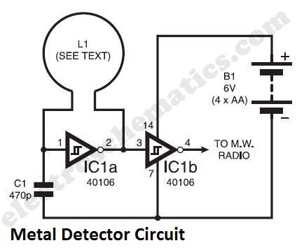
The metal detector circuit presented here exemplifies simplicity while demonstrating effective functionality. It utilizes a single 40106 hex Schmitt inverter IC, a capacitor, a search coil, and batteries. A connection from IC1b pin 4 must be made to a...
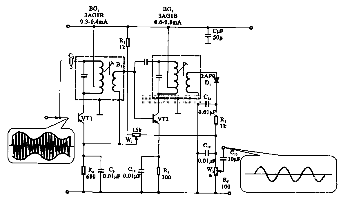
The demodulation and detection circuit is a radio AM intermediate frequency (IF) signal amplifier that performs two-stage detection using diode Dr. It extracts the audio signal from the IF carrier detection and subsequently sends it to the power amplifier...

This circuit employs a diode series clipper to limit noise peaks on a received signal. It is most effective in scenarios where several volts peak-to-peak of audio signal are present. The diode series clipper circuit is designed to protect subsequent...

This ultra-bright white LED lamp operates on 230V AC with low power consumption. It is suitable for illuminating VU meters, SWR meters, and similar applications. The ultra-bright LEDs available in the market range from Rs 8 to 15. These...
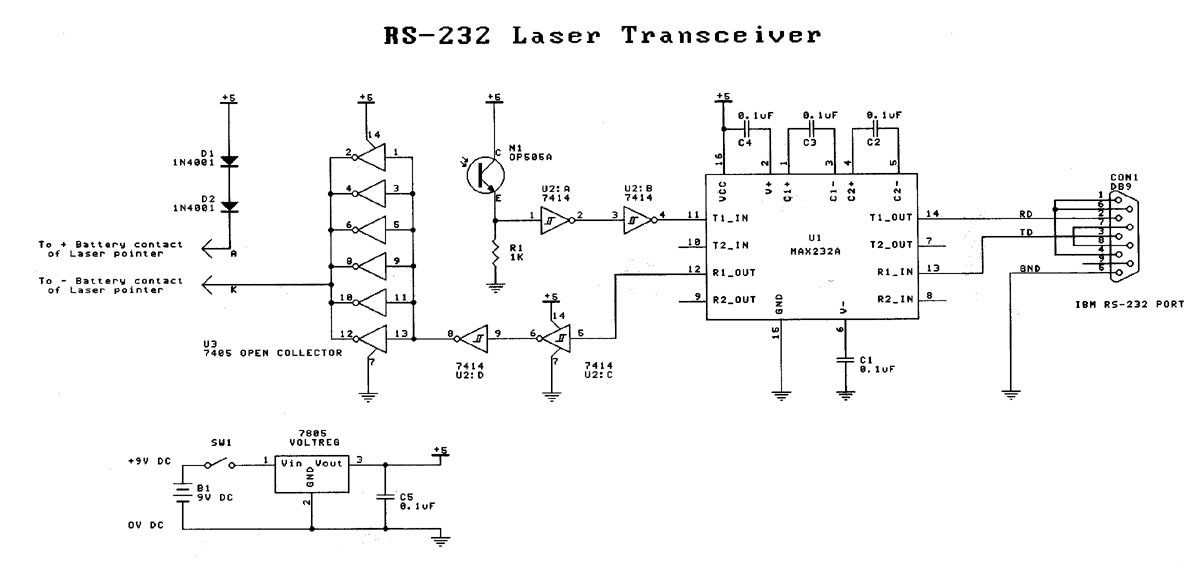
Laser based projects used to be expensive, until the development of solid state lasers. This project is designed for the entry level laser experimenter. The circuit allows any two computers with serial (RS-232) communication capability to communicate over 200...

The circuit is constructed on a breadboard and produces the expected sound characteristics, specifically a damped sine wave reminiscent of large 808/909-style kicks. However, it exhibits a significant amount of noise. An attempt was made to mitigate this by...