
op amp Twin T circuit noisy

The described circuit is a sound synthesis device that utilizes operational amplifiers to generate audio signals, particularly for creating kick drum sounds similar to iconic drum machines. The damped sine wave output is characteristic of the sound design typically sought in electronic music production. The noise issues observed may stem from several potential sources, including inadequate power supply decoupling, grounding problems, or interference from external sources.
To address the noise, it is advisable to implement a more robust power supply filtering strategy. This can include adding additional bypass capacitors (both ceramic and electrolytic) close to the power pins of the operational amplifiers. A combination of smaller capacitors (e.g., 100nF ceramic) and larger electrolytic capacitors (e.g., 10µF to 100µF) can help filter high and low-frequency noise effectively.
Grounding practices also play a crucial role in minimizing noise. A star grounding configuration is recommended, where all ground connections converge at a single point, reducing ground loop issues. Ensuring that the signal ground and power ground are separated until they meet at the power supply can further reduce buzz and hum.
The buzzing sound when touching the potentiometers or wires suggests potential issues with shielding or grounding. Shielded cables should be used for any signal paths, particularly those that are susceptible to interference. Additionally, ensuring that the potentiometers are grounded properly and that their enclosures are connected to ground can help reduce this noise.
Lastly, if the circuit is susceptible to electromagnetic interference (EMI), consider placing the breadboard inside a metal enclosure or using a Faraday cage to shield it from external electromagnetic fields. This can significantly enhance the overall performance and sound quality of the circuit, providing a cleaner output with reduced noise and interference.It`s built on a breadboard and it sounds exactly how it should sound (damped sine wave, big 808/909-kind of kicks). However it`s noisy. I`ve tried adding a big electrolytic cap between V+ and GND. It makes difference yet it`s still very noisy. Also, the circuit tends to `buzz` when I touch the pots or a wire. Any idea how to kill that The whole circuit is powered from a split power supply from a switchable adaptor (I mean the op amp, the rest of the circuit is powered from 0-9V).
🔗 External reference
Related Circuits
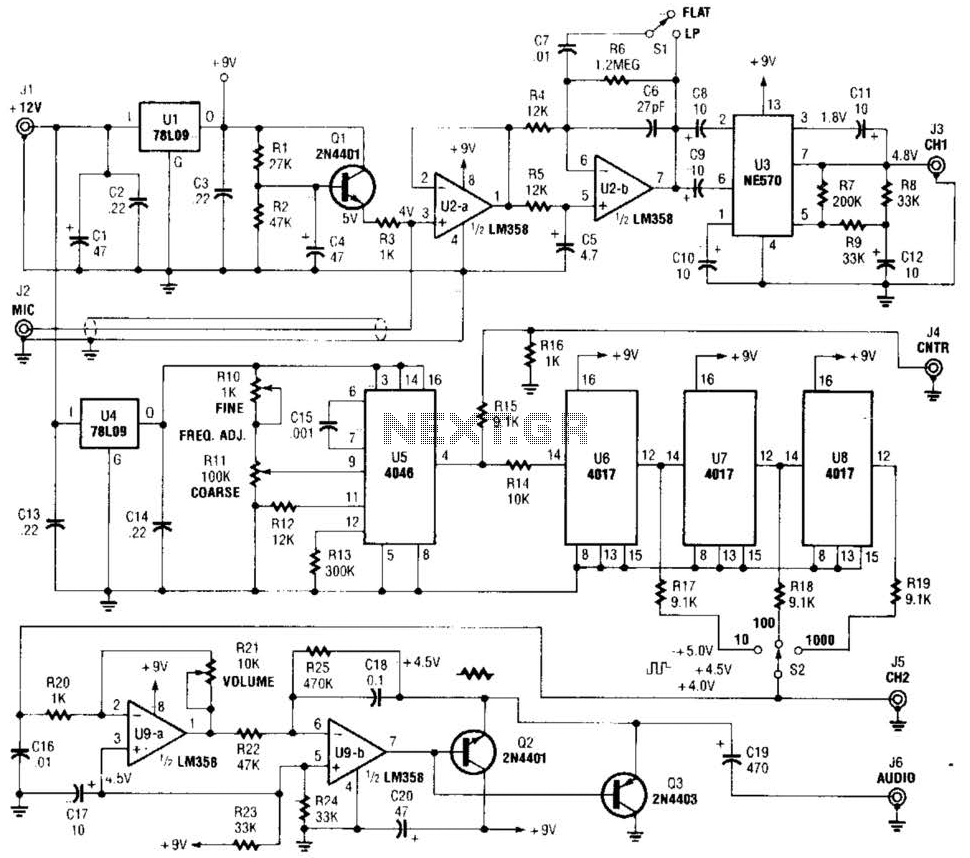
The precision audio frequency generator consists of several sub-circuits: an audio amplifier/filter circuit, an automatic level control, a variable voltage-controlled oscillator, a frequency divider circuit, an integrator, and an audio output amplifier. An electret microphone element is utilized to...
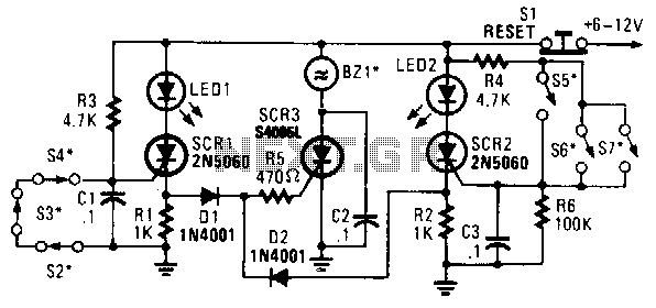
In this circuit, a low-powered silicon-controlled rectifier (SCR) is utilized to trigger a higher-powered SCR. When a switch is opened (S2, S3, S4) or closed (S5, S6, S7), either SCR1 or SCR2 is activated. This action subsequently triggers SCR3...
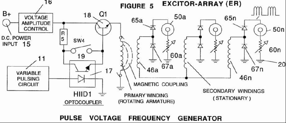
A power supply system utilizes a generator as a source of fuel to separate hydrogen and oxygen gases from natural water. It has the capability to control gas production by varying the amplitude of the voltage and/or the pulse...
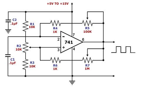
This is a square wave generator circuit. The primary component of this circuit is the 741, a general-purpose operational amplifier. The circuit operates with a single power supply voltage (Vs) that can vary between +5V and +15V. The square...
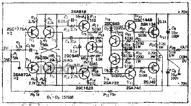
The south circuit consists of four parts, arranged in descending order: an NPN transistor dynamic garbage device (T1), a PNP transistor differential amplifier (T2, T3) forming a double differential circuit, two balanced output amplifiers with opposite phase, and a...
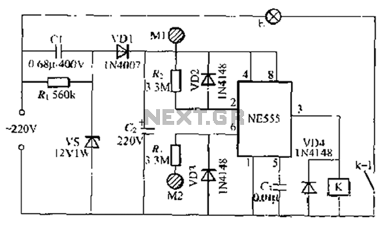
A use NF double touch lamp circuit based on a 55 base design, utilizing switches. It operates with 220V AC and includes a simple composition of a power-saving buck converter in conjunction with a half-bridge circuit. The circuit is...